The darkfield microscope dates back to the early 19th century with some of the developments in optical microscopy. It was then that scientists started conducting experiments on different illumination techniques in a quest to maximize contrast for observing transparent and fragile specimens. Toward the late 1800s, the darkfield technique became quite popular, especially when live microorganisms and unstained biological samples were observed.
This was also the period when the bright-on-dark effect, due to the introduction of the darkfield condenser, came into the picture. This was a revolutionary method through which researchers could study living cells and tiny structures without staining, which often changed or killed the specimens.
Over time, the technique was perfected and evolved into an essential tool in microbiology, cytology, and materials science. Today, darkfield microscopy stands as a valuable method for observing minute details, drawing upon a legacy of continuous innovation.
What is a Darkfield Microscope?
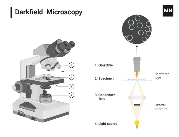
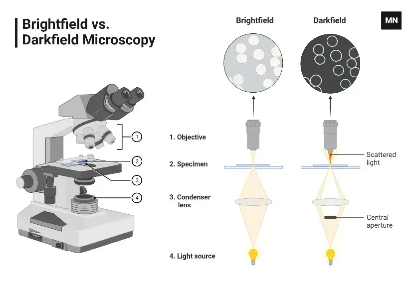
A darkfield microscope is an optical device that highlights specimens by making them appear bright against a dark background, ideal for viewing transparent or unstained samples.
A darkfield microscope is a type of optical microscope that uses a special technique to illuminate the specimen, making it appear bright against a dark background. This technique is particularly useful for observing transparent or unstained specimens. Below are some points about darkfield microscopes:
Illumination method – It directs light so it doesn’t enter the objective lens directly, only scattered light from the specimen is seen.
Useful for Viewing– small, delicate samples like bacteria, blood cells or other transparent organisms.
They don’t require staining– which helps in preserving the natural state of live samples.
Contrast enhancement: It’s mainly used for samples with low inherent contrast.
The light source– is often a bright LED or halogen lamp, modified with a darkfield stop.
Often paired with– other microscopy techniques for comprehensive analysis.
It’s widely used in – microbiology, cytology, and materials science.
Not suitable for– thick or highly absorbent samples, as they may block light completely.
Principle of the Darkfield Microscope
The principle behind the darkfield microscope is quite simple, yet effective. It works by blocking out the direct light source, causing the light to scatter when it hits the specimen. In this setup, the objects that have refractive values close to that of the background will appear bright against a dark backdrop, making them easier to view.
Like most microscopes, the darkfield microscope operates based on light interactions. When light hits an object, the rays scatter in all directions, or azimuths. The special design of this microscope removes the scattered light, also known as zeroth order, so that only the scattered beams reach the specimen.
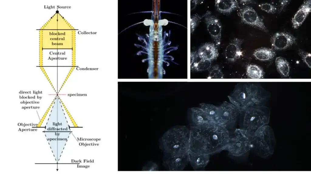
To achieve this, a condenser and/or stop is placed beneath the stage. This ensures that the light rays strike the specimen from different angles, rather than just directly from above or below. The light, scattered in various directions, creates a “cone of light” that interacts with the specimen.
When the rays diffract, reflect, or refract off the object, the result is an image in dark field—where the specimen appears illuminated against a dark background. It’s a clever way to enhance contrast without needing a direct light source to shine on the object. The principle of this microscope relies heavily on how the light interacts with the sample.
LED illuminators- often used in dark field microscopes, are specially designed to complement this unique light-scattering phenomenon. The scattered rays hit the sample, allowing for a better view of objects that would otherwise blend in with the background.
In a stereoscopic microscope, the light path is arranged differently, and the results—though related—aren’t the same. The design of a dark field microscope specifically eliminates the direct light rays, focusing on only the scattered rays, thus making it distinct.
It’s a fascinating process, right? Instead of just blasting the sample with light, the darkfield method creates an illusion that the specimen is floating, highlighted against a pitch-black background. Definitely an interesting approach!
How does Darkfield Microscope Works?
Darkfield microscopy – It works by illuminating the sample at an oblique angle using a special light source.
The light is scattered by the specimen, and the scattered rays reach the objective lens. The result is a bright, illuminated specimen against a dark background.
The condenser lens- It plays a big role in darkfield illumination. It has a special diaphragm that ensures light doesn’t directly enter the objective lens.
Just like most microscopes, the objective lens captures the scattered light – that’s how the image is formed.
It helps in viewing objects that are too small or have very low contrast – such as bacteria or fine details of a cell.
The sample is usually very thin and unstained, so, yeah, it’s ideal for live specimens.
LED illuminators – commonly used to produce the right amount of light for darkfield. Some systems use halogen or tungsten lamps too.
It’s often used in microbiology or medical research – allows fine details to be visible without needing dye.
Another thing, Darkfield microscopes provide high contrast and detailed images, which are great for objects that are transparent or nearly invisible in other lighting conditions.
Light passes through the sample from the sides, and the center doesn’t collect any light – hence the dark background.
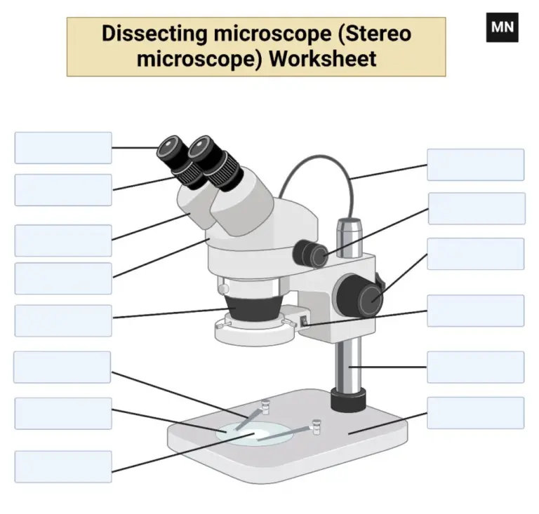
Dark-Field Microscope
Parts of Darkfield Microscope
Condenser lens – The key part for darkfield; directs light at an angle so that only scattered light enters the objective.
Illuminator – Provides the light source. LED illuminators are commonly used, but some systems still use more traditional halogen bulbs.
Objective lens – This is where scattered light is gathered, creating a contrast-rich image, and usually has higher magnification.
Stage – The flat platform where the sample sits; it’s adjustable so you can move the specimen around to examine it.
Diaphragm – It’s part of the condenser; it controls the amount of light hitting the sample, crucial for the darkfield effect.
Eyepiece – The lens through which you view the image. It magnifies the image created by the objective lens.
Base – The bottom part that holds everything together. It usually houses the light source and provides stability.
Arm – Connects the stage and the base, and supports the eyepiece and other parts.
Mechanical Stage – Some advanced darkfield microscopes come with this for precise control of specimen position, often used in research.
Focus knobs – These control the sharpness of the image by adjusting the distance between the stage and objective lens.
Mirror – Reflects light from the illuminator into the condenser, helping to direct it properly for darkfield effect.
Operating Procedure of Darkfield Microscope
Set up the microscope – Place your darkfield microscope on a stable surface, ensuring that the power is off before connecting the light source.
Select appropriate lighting – Turn on the light source, typically an LED or halogen bulb, and adjust the brightness to a moderate level.
Adjust the condenser – Make sure the condenser is properly aligned for darkfield illumination. Adjust it so that the light enters the sample at an oblique angle.
Position the sample – Place the specimen on the stage. If you have a mechanical stage, use the controls to place the sample precisely in the centre.
Set up the diaphragm – Adjust the aperture diaphragm under the condenser to ensure that only scattered light reaches the objective lens.
Choose the objective lens – Start with a low magnification objective lens and gradually increase magnification as needed.
Focus the specimen – Using the coarse focus knob, bring the sample into rough focus. Then, use the fine focus knob to get a clear, sharp image.
Observe the image – Look through the eyepiece and fine-tune the focus as required. You should see a brightly illuminated specimen against a dark background.
Adjust light and contrast – If the image is too dark or too bright, adjust the light intensity and diaphragm. Fine adjustments ensure optimal contrast.
Switch to higher magnification – Once the image is focused, switch to a higher magnification lens to observe finer details of the specimen.
Record your findings – Take notes or capture images if your microscope has a camera attached.
Dark-Field Microscope
Operating Procedure of Darkfield Microscope
Prepare the sample- Position your specimen on the stage, centering it correctly. Clean and align it to view clearly.
Switch on the Microscope- Power on the system and check if the light source is on. This is the step to ensure that the microscope is ready for use.
Adjust the Illumination- Tune the light source. If using LED illumination, check if it is bright enough to offer the best contrast. The light needs to be angled so that it does not penetrate the objective lens directly.
Adjust the condenser- The condenser needs to be set up correctly for darkfield microscopy. This will allow the light to go through the sample instead of directly into the lens. Raise it up high so that it will do that.
Check the diaphragm –it needs to be small, focusing light around the edges of the sample.
Select the objective lens- Like most microscopes, choose the correct objective lens- typically 40x or 100x for darkfield work. Mount and focus with the coarse adjustment knob. The fine adjustments can be made afterwards.
Fine Focus- To enhance the resolution of the image even more, turn the fine focus knob. The sample should be bright against a dark background. Note that the resolution is very sensitive to contrast, and darkfield is no exception.
Adjust the Aperture- Now adjust the aperture to maximize the contrast. Darkfield microscopy is fundamentally about showing the edges of your sample while keeping the center in obscurity. Be careful not to overdo this; it might become too blinding.
Observe the Sample— Finally, look at your specimen. The edges should be bright, while the center should be shrouded in obscurity. If you cannot see a sharp edge, you may need to fine-tune the condenser or objective lens.
Switching Between Objectives- If you want to zoom in, switch carefully to a higher magnification. Be sure to refocus after changing objectives. Do not move the stage too abruptly when changing lenses.
Cleanup- When finished, carefully remove the specimen. Switch off the illumination and power down the microscope. Cover the microscope with a dust cover to protect the lenses from dust buildup. Clean the lenses gently with lens cleaning tissue to prepare for the next session.
Uses of Darkfield Microscope
Darkfield Microscopes are widely used to examine live, unstained specimens. This technique allows the observer to view translucent or transparent objects, such as bacteria or plankton.
Used for observing the fine details of the structure of cells, especially when looking at specimens that don’t naturally have significant contrast.
Ideal for examining thin, delicate, and small biological samples. These microscopes provide bright, almost fluorescent images, even without staining.
Popular in microbiology and diagnostic laboratories, especially for observing pathogenic bacteria like Treponema pallidum (which causes syphilis) or the Borrelia species (causing Lyme disease).
Helps to visualise samples that might otherwise require heavy preparation, which can often distort or kill the specimen. It’s good for live bacteria, fungi, and other microorganisms.
Essential in detecting cell structures, particularly in medical fields, where observing bacteria or viruses can provide valuable diagnostic information.Also used in research for studying the finer details of living tissue, blood cells, or even certain types of crystals.
The dark background that results from this type of illumination makes the sample appear bright and clear—this is especially helpful when traditional staining or contrast techniques might alter or destroy the sample.
Advantages of Darkfield Microscope
Darkfield microscopy – it enhances contrast without the need for stains, making it easier to observe living cells.
Unlike Brightfield, it allows for the clear viewing of specimens that are nearly invisible under regular light conditions.
No need for complex preparation methods, such as staining, which can sometimes damage delicate samples.
The “glowing” appearance of specimens under darkfield illumination makes it easier to see fine details that would otherwise be missed.
It’s commonly used for studying live microorganisms, bacteria, and small, transparent objects in fluids.
Theres also the fact that this method is great for revealing edges and outlines of structures.
High-resolution, detailed images of small or nearly transparent particles – it’s ideal for certain biological samples.
You can view specimens in their natural, unstained state, preserving their natural structure and characteristics.
Useful in microbiology labs, especially when working with microorganisms that don’t naturally take up stains.
Darkfield helps with faster, more efficient imaging, particularly in fast-paced environments or when working with delicate samples.
Limitations of Darkfield Microscope
Darkfield microscope – it can be tricky to use for thick specimens, as the contrast may not be sufficient to reveal all details.
The light source can be quite intense, which can cause some samples to overheat, potentially damaging delicate specimens.
It’s a bit difficult to set up, requiring precise alignment of the condenser and light source, which can be time-consuming.
Low magnification – well, it’s not always the best choice for high-power viewing or observing structures at very fine scales.
The images produced can sometimes appear grainy or have a low signal-to-noise ratio.
It doesn’t provide as much depth of field as other techniques, so focusing on thicker samples can be hard.
Darkfield microscopes tend to have a limited field of view compared to other types.
Some specimens might appear with halo-like artifacts around them, causing distortion.
It can be hard to interpret the images without experience, especially if you’re used to more conventional techniques.
High cost – yes, the equipment and maintenance can get expensive, especially when compared to simpler setups.
Because it’s a bit challenging to maintain, dirt or dust can easily reduce image quality.
Difference between dark field and bright field Microscope
Reference
Madigan Michael T, Bender, Kelly S, Buckley, Daniel H, Sattley, W. Matthew, & Stahl, David A. (2018). Brock Biology of Microorganisms (15th Edition). Pearson.
Procop, G. W., & Koneman, E. W. (2016). Koneman’s Color Atlas and Textbook of Diagnostic Microbiology (Seventh, International edition). Lippincott Williams and Wilkins.
Fluorescence microscopes—have you ever wondered how scientists capture such vivid, glowing images of cells, tissues, or even bacteria? This is where fluorescence microscopes come into play, using fluorescence and, at times, phosphorescence to reveal the hidden intricacies within both organic and inorganic materials. It is like magic, but it is based on the science of light and fluorescence.
In short, these microscopes rely on two fascinating processes: fluorescence and phosphorescence. Fluorescence is the phenomenon whereby a substance absorbs light and then emits it at a longer wavelength, which gives it a glow often so beautiful to see. Imagine it as a flash of light that disappears almost instantly. In contrast, phosphorescence is similar but occurs more slowly; the light lingers in the air for a longer time. Both are important in the operation of these microscopes, but it is fluorescence that is the main event.
Now that’s interesting: Do you know that fluorescence microscopy was at one time perceived not as an easy-to-handle instrument? At a time when the technique was still in its infancy, scientists such as August Köhler, Carl Reichert, and Heinrich Lehmann saw fluorescence primarily as an interfering element, particularly with ultraviolet microscopy. If we now jump forward to the early 20th century, Otto Heimstaedt and Heinrich Lehmann built the first practical fluorescence microscope. To their surprise, even bacteria, plant tissues, and animal cells had a natural glow!
Now that we’ve warmed up a little, let’s take a bit of a detour before discussing how fluorescence microscopy actually works. Do you know of the term “Stokes shift”? No, it’s not the latest dance craze! This shift describes a phenomenon found by British scientist Sir George G. Stokes in 1852, wherein light emitted after excitation has its wavelength shifted toward longer, lower-energy wavelengths. Stokes’ finding was fundamental in establishing the principle of fluorescence that would eventually become the basis of fluorescence microscopy.
It is like that in real life, too. When you shine ultraviolet or visible light on a sample, you are energizing the molecules within that sample so they radiate light when they relax back into their previous states. Now, here’s the neat part: The wavelength of light coming off of that molecule is greater than the wavelength of the light it had absorbed, and this is what causes that pretty glow we see with our microscope.
But that’s not all! Fluorescence microscopy is more than a visual spectacle; it is the art of labeling. To see most samples, researchers must coat them with fluorescent dyes or molecules. However, some tissues have a natural ability to fluoresce on their own; that is autofluorescence and does not require tagging. Maybe you have ever seen glowing DNA inside a cell; this is because of applying fluorescent stains, such as Hoechst or DAPI. Other dyes, such as Phalloidin, highlight actin filaments, giving us a snapshot of cell structures.
Let’s not forget about the fluorochromes – Isothiocyanate, Alexa Fluors, or Dylight 488, which are used to mark the target samples. Even antibodies can be labeled with these fluorochromes to help detect antigens.
Fluorescence microscopy has changed the way we study cells and tissues in the grand scheme of things. It’s like having a superpower: the ability to illuminate the unseen world at a microscopic scale. From understanding the inner workings of cells to investigating disease mechanisms, this technique has opened new frontiers in biological research.
Principle of Fluorescence Microscope
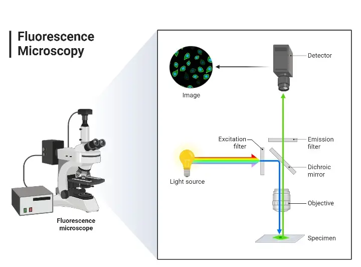
The first step of the observation of the sample in the fluorescence microscope is that the sample is tagged using fluorescent dyes. Subsequently, a white light source which is allowed to fall on the excitation filter. This particular filter selects light of a given wavelength that would be able to excite fluorescent molecules tagged within the specimen. The excitation light falls on the dichroic mirror. The reflected light from the dichroic mirror passes to the specimen when it comes out of the objective lens. These small wavelength light falls on the specimen that contains a fluorescent dye. It produces emission of the high wavelength of light which travels again through the condenser lens and dichroic mirror. This way green light in the maximum amount along with some blue passes towards the emission filter. This filter lets the longer wavelength green light enter into the eyepiece and detector but rejects all of the blue light. The detector collects this green light and reflects back through to the specimen to make the specimen emit a fluorescent green image on a black background.
Parts of a Fluorescence Microscope
Light Source- Traditionally, it is usually a mercury or xenon arc lamp, providing an extremely bright source of light and has a very broad spectrum of light with both UV and visible wavelengths; such a broad spectrum is required for exciting a variety of fluorophores in the sample.
Excitation Filter – It is placed in the light pathway. This filter allows through only the desirable light that excites the fluorophore into a fluorescent state, while allowing some wavelengths of the light source to pass through.
Dichroic Mirror- It is sometimes called a dichromatic mirror or beamsplitter. The excitation light reflects onto the specimen while allowing the fluorescence emitted to pass through towards the detector. The selective reflection and transmission of dichroic mirrors are important in separating excitation from emission light.
Objective Lens- It is a biconvex lens which serves as the lens for focusing excitation light on a specimen and collecting emitted fluorescence. Among all the lenses placed within a microscope, the objective lens has the strongest influence on the resolution and brightness of the image obtained.
Sample Stage– This is the stage that holds the specimen and allows for accurate movement in the x, y, and z axes. This is very important for focusing or scanning areas of interest in the sample.
Emission Filter – This is the component that the emitted fluorescence passes through after it passes through the objective lens. This filter blocks residual excitation light and transmits only the wavelengths of the emitted fluorescence, meaning that the detected signal is due to the fluorophores.
Detector – Detectors may be photomultiplier tubes, charge-coupled devices, or any other device that converts the transmitted fluorescence into an electronic signal and would eventually be processed to form an image. The detector chosen determines the sensitivity and resolution capabilities of the imaging system.
Eyepieces and Camera- The eyepieces are used to allow direct observation of the specimen by the naked eye of the observer. The camera makes images, thereby recording and further analyzing. Many modern systems have the camera built into the optical path, thus permitting simultaneous viewing and imaging.
Fluorescence microscope diagram
Types of Fluorescence Microscope
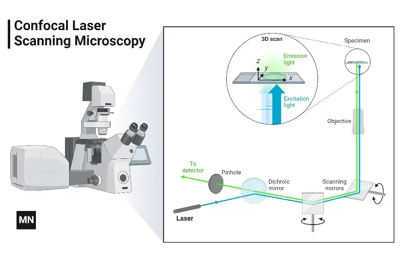
Wide-field Epifluorescence Microscopy- In this approach, the entire sample is illuminated simultaneously by the excitation light. This is a simple technique commonly used for routine fluorescence imaging.
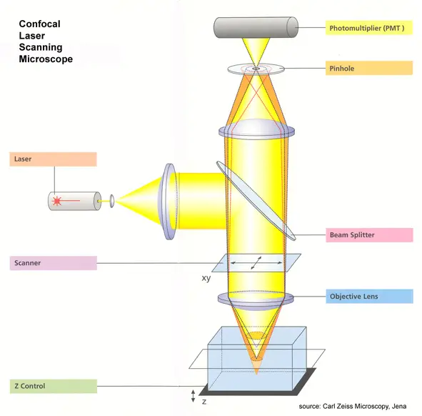
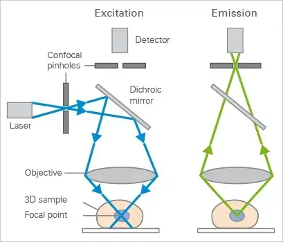
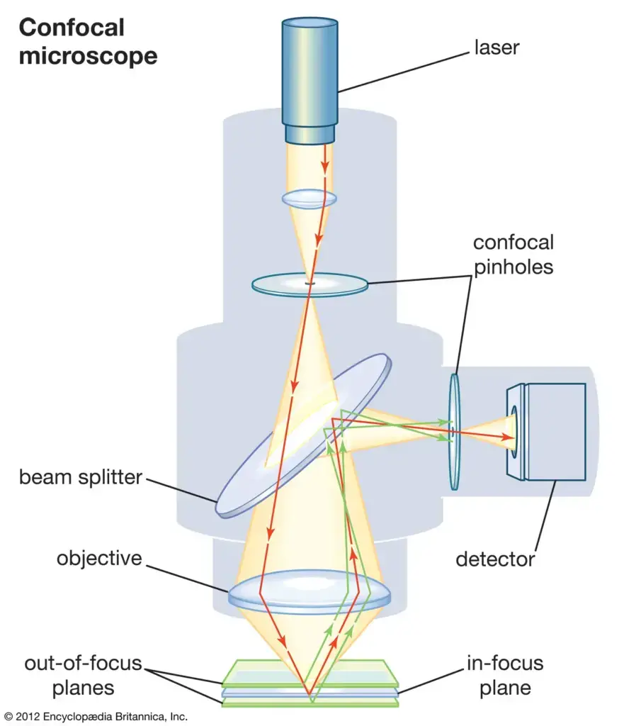
Confocal Microscopy- Here, the source of light is a laser that scans the specimen point by point and collects emitted light through a pinhole that removes unwanted out-of-focus light. It produces high-resolution optically sectioned images.
Multiphoton Microscopy – Here, two or more photons of lesser energy excite fluorophores, and it has deeper penetration into the tissue with less phototoxicity. It is useful mainly in imaging thick samples.
Total Internal Reflection Fluorescence (TIRF) Microscopy– TIRF microscopy restricts illumination to the near-surface region of the specimen alone. It is used to study cell membrane and interfacial interactions.
Epi-fluorescence Microscopes – Here, the illumination and detection happen from the same side of the specimen. They are utilized in routine fluorescence imaging.
Inverted Fluorescence Microscopes – Objectives and the light source are attached from below to observe the living cells right within the culture dishes.
Operating Procedure of Fluorescence Microscope
The working of a fluorescence microscope requires extreme care so that the images produced are highly accurate and the sample is not compromised. Below is a general protocol for working with a fluorescence microscope:
Sample Preparation- Verify that the sample has been appropriately prepared and stained with appropriate fluorophores.
Slide Placement- Place the sample on an uncontaminated microscope slide and place a cover slip over it. Microscope Setup:
Power On- Turn on the main power supply and then turn on the microscope using the power switch located on the right side of the base. Engage the illumination source, which could be a mercury or xenon lamp, by pressing the ‘LIGHT ON’ button. Choose the appropriate objective lens, such as 10X, 20X, 40X, or 100X, by turning the objective selection wheel. Adjust lighting and filtering
Excitation Filter– Select appropriate excitation filter according to fluorophore in use.
Dichroic Mirror: Mount dichroic mirror so as to reflect the exciting light towards sample and reflected fluorescent light towards the detector.
Emission Filter – Set emission filter to pass light of specific wavelength emitted by fluorophore
Coarse Focus – Use the coarse focus knob to bring sample into general focus.
Fine Focus – Fine-tune the focus with the fine focus knob for clear image clarity.
Adjust the Illumination – As required, change the intensity of illumination for ideal brightness in the image
Capture Images – Utilize the camera system to take images of the fluorescence.
Overlay Channels– In case imaging multiple fluorophores, overlay the images for visualizing colocalization
Turn off the Light Source and Microscope– Turn off the light source and microscope once imaging is completed.
Save the Captured Images and Data– Save and backup all captured images and data.
Clean-up– Wipe the microscope stage and other parts that could have been in contact with the sample.
Applications of Fluorescence Microscope
Cell Biology – In cell biology, scientists commonly use fluorescence microscopes to observe various parts of cells, including proteins, nucleic acids, and lipids. These parts can be tagged with fluorescent tags.
Immunofluorescence – The microscope enables researchers to use specific antibodies that are attached to fluorescent dyes to identify antigens in tissue or cell samples. Such techniques are also commonly applied in diagnostics.
Live Cell Imaging– Unlike the conventional microscopes, fluorescence microscopes can be used for live cell imaging. It is feasible to observe living cells in real time using the appropriate fluorescent dyes, which will provide an understanding of division, movement, or apoptosis processes.
Molecular Biology– The method is also used in molecular biology to study gene expression, localization of proteins, and their interactions inside the cells. Fluorescent probes are used to track interactions at the level of molecules inside the cell.
Biomedical Research – In research related to cancer, infection, and neurological diseases, the fluorescence microscope helps identify specific cell markers or track pathogens. It helps with identifying the location of biomarkers in tissue samples.
Microbial Detection – For microbiological studies, fluorescent microscopes enable the detection of specific microorganisms by labelling with fluorescent dyes. It helps in detecting bacteria, fungi, viruses etc. This is often more sensitive than traditional light microscopes.
Environmental Studies- Fluorescence microscopy is applied to environmental samples such as water, air particles, or soil. It enables the tracking of microorganisms or pollutants through the use of fluorescence markers. Like other microscopes, it provides critical information on biodiversity of ecosystems.
Forensic Science – In this science, fluorescent microscopes are used to study biological evidence, like blood or fibers, in crime scenes. It can also reveal traces of drugs or harmful substances in hair or tissue samples.
Pharmaceutical Industry – Researchers use fluorescence in drug development in order to know how drugs work with cells or how the shape of different kinds of cells is changed.
Fluorescence Microscopy- Imaging Specifics – Different types of fluorophores, such as those mentioned, exist for fluorescence microscopy. During marking and visualization of living cells, some of them are used. These selections of dyes become dependent on a sample; whether one requires finer details or how it is meant to be used.
Advantages of Fluorescence Microscope
High Sensitivity – Fluorescence microscopes are very sensitive. They can see extremely low amounts of light, which helps find very small amounts of biological molecules. This is one reason why they are highly popular in diagnostic research.
Multicolour Imaging – This is a huge advantage! Multiple fluorescent dyes can be used simultaneously, allowing the observation of several components in a single sample. This helps in visualising complex interactions or co-localisation of molecules. Like most light-based microscopes, the clarity of the image doesn’t suffer with the addition of more colours.
Non-invasive – Fluorescence microscopy typically does not damage cells. It is particularly useful for examining living cells. Scientists can observe cells or tissues with minimal damage. This is extremely useful for observing living biological processes!
High Resolution Imaging – Using the proper equipment and fluorescent labels, fluorescence microscopes can obtain clear images. This allows scientists to view the small details of cell structures, sometimes even at a molecular level.
Quantitative Analysis – Fluorescence microscopy lets us measure things accurately, like how strong the fluorescence is. This helps us check how much of certain molecules are in a sample.
Deep Tissue Penetration – Regular fluorescence does not go deep into tissues, but new methods like two-photon microscopy allow us to see deeper in thicker tissue samples. This has greatly helped its use in biomedical research.
Versatile – Fluorescence microscopes can be used for a wide range of applications, from examining the cell and tissue structure to watching active processes like how enzymes work and how genes are expressed.
Speed – Fluorescence microscopy can give results relatively quickly, especially when looking at live images, which is useful for observing fast biological processes such as cell division or changes in protein activity.
Specificity – Fluorescence allows for the identification of molecules clearly. Once specific antibodies or molecules are tagged with fluorescent dyes, it is easier to find and trace proteins, DNA, and other parts of the cell in mixed samples.
Excellent For Small Samples – It is useful for small sample sizes or even when working with small amounts of material. This technique can easily detect even the smallest amount of a labelled molecule, which makes it popular for single-molecule imaging applications.
Limitations of Fluorescence Microscope
Photobleaching – Photobleaching is the phenomenon of degrading fluorescent dyes with time under the influence of light. This limits both the time of observation and quality of long-term imaging. Once a fluorophore loses its brightness, the image obtained is very difficult to interpret.
Low Penetration Depth – Although there is tremendous progress in the invention of two-photon microscopy, fluorescence microscopes cannot still penetrate deep in thick specimens. This limits observing some tissues or organisms at depth unless special techniques are used.
Fluorescence Overlap – Many fluorophores could emit light in similar wavelengths that lead to overlap in fluorescence. This causes confusion in multi-color imaging and does not distinguish easily between the various components in the sample.
Complex Sample Preparation- Much of the work of preparing samples for fluorescence microscopy requires the use of labeling with specific dyes or antibodies. This alone could be a rather time-consuming process and thus prone to mistake, especially with living cells.
Costly Instrumentation-The expensive fluorescence microscopes that are required in techniques such as confocal or two-photon microscopy may be very costly for some laboratories and, therefore, impractical to purchase.
Requires Highly Skilled Operation – Fluorescence microscopy is not as straightforward as compared to the use of a regular light microscope. It requires an immense level of skill in setting up the microscope correctly, picking the proper dyes, and interpreting results accordingly. Proper conditions might not be met if a misinterpretation may occur.
Phototoxicity –The reason for phototoxicity is that light needed to excite fluorescent dyes will damage the living cells. In fact, longer illumination at a higher intensity puts a sample in jeopardy, particularly with sensitive or living cells. Thus, it becomes problematic in maintaining prolonged imaging for specific research.
Signal-to-Noise Ratio – In other cases, background fluorescence may compete with the signal created by labeled molecules and, consequently, may lead to lower signal-to-noise ratio. Blurring images caused by interference from background fluorescence might make it very hard to determine faint signals.
Limited by the Properties of Fluorophores – Again, the brightness, stability, and photobleaching rate of the fluorophores determine the qualities of images that can be acquired. If the wrong dye is used for a sample or an experiment, the resultant data may not be very accurate or entirely easy to understand.
Size and Portability – As compared to relatively simple microscopes, fluorescence microscopes tend to be fairly large and immobile, and this may hinder their use in field studies or anywhere mobility is paramount.
Depth of Field – Fluorescence microscopes often possess a shallow depth of field especially when high magnification is utilized. This property makes it difficult to obtain a proper image of more substantial samples, especially without adjusting the focus from one plane to another.
Reference
Sanderson MJ, Smith I, Parker I, Bootman MD. Fluorescence microscopy. Cold Spring Harb Protoc. 2014 Oct 1;2014(10):pdb.top071795. doi: 10.1101/pdb.top071795. PMID: 25275114; PMCID: PMC4711767.
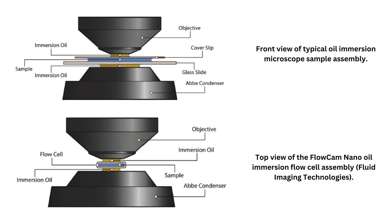
The oil immersion technique is a method used in microbiology to increase the resolution of a microscope when examining specimens at high magnification. By applying a special oil (usually immersion oil) between the lens and the slide, it enhances the clarity of the image.
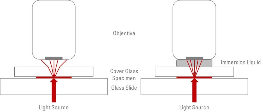
Why is oil necessary? It’s all about improving light transmission. Without it, light refracts as it passes through the air, distorting the view. Oil, however, has a similar refractive index to glass, ensuring light passes through smoothly.
The process involves placing a drop of oil directly onto the specimen, then carefully positioning the objective lens to immerse in the oil. This minimizes refraction, making the specimen appear clearer and more detailed under the microscope.
This technique is particularly useful for viewing specimens at higher magnifications (typically 100x), where the detail is most critical. Think of it like getting a clearer view through a foggy window—without oil, the specimen can appear blurry.
While the oil immersion technique is essential for high-quality viewing, it’s important to clean the lens and slide thoroughly after use. A small amount of oil left behind can damage lenses or cause the image to blur during future use.
The technique requires some finesse. Rushing can lead to air bubbles or improper positioning of the lens, both of which can ruin your observations.
In practice, the oil immersion technique is indispensable in fields like bacteriology and pathology. It’s the difference between seeing a general blur and identifying the intricate structures of cells or microorganisms.
So, when you look through the microscope and see that amazing, detailed image, thank the oil! It’s the unsung hero of high-resolution microscopy.
Oil immersion is one of the techniques used in microscopy that highly improves the resolving power of a microscope by utilizing a transparent oil with a refractive index nearly equivalent to that of glass. It involves putting a drop of immersion oil between the objective lens and the specimen such that light will pass through with minimal refraction, which, in turn, increases the sharpness and definition of an image.
Purpose – To increase the numerical aperture of the objective lens so that the resolving power of the microscope is improved.
Application – Mostly used in high magnification microscopy, for example in observing the cellular fine structure or small microorganisms.
Considerations – Suitable for those specimens that remain stationary and a few micrometers in thickness.
Why is Oil Immersion used?
Oil immersion is a technique used in light microscopy to enhance both image quality and resolution. The main reasons for oil immersion are:
High Refractive Index – Oil immersion oils have a very high refractive index, around 1.515, close to that of glass. This reduces the amount of refraction happening in the light as it passes from the specimen through the cover slip and into the objective lens, allowing more to be captured.
Reduced Air Gap– The immersion technique increases the numerical aperture (NA) of the lens system by substituting the air gap that is present between the objective lens and the cover glass with oil. An increased NA allows for the collection of much more light; hence, this provides enhanced resolution and clear images of very small structures. Improved Image Quality
Brighter Images- The use of immersion oil results in brighter images than those taken without it. This is because more light is transmitted and the scattering effects are reduced when light travels through oil rather than air.
Higher Contrast- In addition, oil immersion can greatly increase the contrast in images, making it easier to distinguish fine details in specimens, such as cellular structures or small organisms. Ideal for High Power.
Suitable for Small Specimens- Oil immersion is particularly advantageous when examining small specimens measuring 1 to 2 micrometers in size or less, and when using high magnification objectives often over 100x. This means a much finer view of structures such as bacteria or cellular organelles that could easily be missed at lower magnifications.
Objectives of Oil Immersion Technique
Better Resolution – The oil immersion method makes the resolution of the microscope better because the bending of light is reduced. This creates clearer and sharper pictures.
More Light Gathering – The objective lens captures more light when using immersion oil, making the image brighter and clearer.
Higher Magnification– It allows clear viewing at higher magnifications, usually 100x, which would otherwise make images blurry without the oil.
Better Contrast – This technique makes the image clearer, showing more of the small details of the specimen.
Reduced Light Scattering – the oil ensures that only the maximum available light is forwarded to the objective lens, thereby producing a better-illuminated image and reduced scattering of light.
Oil Immersion Technique. Image is modified from https://www.labcompare.com/10-Featured-Articles/349589-Extending-the-Limits-Oil-Immersion-Flow-Microscopy/
Immersion oil Types
Synthetic Oil– is a type of oil that is made from cleaned petroleum products. It has high clarity and little optical distortion. It is used in advanced microscopy.
Natural Oil – For instance, these are plant-derived oils, such as cedarwood or clove. They were natural products consumed by people, but they are not as frequently applied currently because of the existence of artificial products.
Cedarwood Oil is a natural oil with a high refractive index. It is sometimes used in labs for special optical needs.
Type A Oil is an immersion oil with a refractive index approaching to about 1.515, which makes it highly suited for general laboratory work using 100x objective lenses.
Type B Oil – Higher-grade immersion oil that has a refractive index close to 1.518; it is intended for more specific high power microscopes and therefore gives clearer pictures.
Immersion oil Technique Procedure
Prepare the slide by gently placing the specimen on the glass surface. Don’t forget to add a drop of immersion oil directly atop the specimen.
Use the 100x objective lens or the oil immersion lens. Take extreme care in rotating the objective lens to avoid breaking the slide.
Now lower the objective lens very gently and keep it suspended immediately above the surface of the slide, so that it just touches the slide surface. Oil will then make an ideal optical path between the specimen and the lens.
Now, once the lens is held firmly in place, rotate the fine focus knob gently to bring the image into focus. The immersion oil will offer a more precise, high magnification view of the specimen.
Adjust the light; sometimes you have to change the intensity on the microscope, especially when using oil immersion, as it may require extra illumination.
After use, the objective lens should also be cleaned gently using lens paper and an appropriate cleaning solution to remove the remainder of the oil. If it is not intended to be reused, then it should be cleaned as well.
Advantages of Immersion oil Technique
Increased Resolution – Immersion oil has a higher refractive index than air. That means it collects more light and, thus, provides a sharper, clearer image. That adds to resolution.
Higher Magnification– It works very well with specimens viewed at higher magnifications, especially at 100x objectives that can reveal more details.
Improved Light Transmission – The use of immersion oil reduces the loss of light due to refraction, thus making the image brighter and more contrasted.
Improved Contrast of the Image– The oil has special optical properties that make the minute details of transparent specimens visible.
Reduced Aberrations– The oil reduces optical aberrations such as spherical and chromatic distortion, thus making the image more precise.
More Accurate Viewing – For some samples, immersion oil ensures that light travels straight between the objective lens and the sample for a much clearer image.
Wider Field of View – The oil captures extra light for an improved total field of view as compared to dry objectives.
Limitations of Immersion oil Technique
Messy Cleanup– Immersion oil used in a lens or slide has to be cleaned off very carefully; otherwise, streaks may form, leaving residues or even damaging the optics.
Special Maintenance Needed – Continuous usage of immersion oil wears off the lenses when not maintained correctly. Lenses need to be cleaned regularly to prevent the buildup of oils.
Limited to High Magnification– It is used mainly at high magnifications, which are mostly at 100x, and is not so effective in tasks where low or medium magnification is needed.
Risk of contamination– If not handled appropriately, the oil contaminates either the sample or the lens and may interfere with the clarity of the image.
Expensive- The oil itself does not bear a price tag, but frequent use of the oil in the laboratory may incur money in the form of products for maintenance and cleaning.
Interference of Oil with Specimens- Sensitive or even living specimens may not be suitable for immersing in immersion oil as it would alter the appearance of the specimen or damage the sample.
Limited Depth of Field – At very high magnifications, even with immersion oil, the depth of field is pretty shallow, so focusing is somewhat of a task.
Transmission Electron Microscope (TEM) – A TEM is a high-resolution microscope that uses a beam of electrons to pass through a thin sample, creating detailed images of the internal structure at the atomic or molecular level. It is used in material science, biology, and nanotechnology to examine ultrastructure.
This is one of the powerful electron microscopes that function on a beam of electrons that focuses on a specimen, thereby producing a highly magnified and detailed image of the specimen.
The power of magnification is much more than 2 million times better than that of the light microscope and produces the image of the specimen which in turn, allows the easy characterization of the image in its morphological features, compositions, and crystallization information as well.
Early discovery of cathode rays, like electrons, by Louis de Broglie in the early 1920s opened up a route to developing the electron microscope that utilized a beam of electrons to create a form of wave motion.
Magnetic fields worked as lenses for the electrons. From these inventions, the first electron microscope was invented by Ernst Ruska and Max Knolls in 1931 and transformed into a Transmission Electron Microscope (TEM) by Ernst Ruska with the help of Sieman’s company in 1933.
There are several advantages of this TEM microscope as compared to the light microscope whose efficiency is also very high.
Among all microscopes both light and electron microscopes, TEM are the most powerful microscopes used in laboratories. It can magnify a mall particle of about 2nm, and therefore they have a resolution limit of 0.2um.
Principle of Transmission Electron Microscope (TEM)
The TEM is based on the fundamental principle of substituting electrons instead of light for producing high-resolution images of specimens. In contrast to the light microscopes, which utilize visible light, the TEM makes use of a highly focused beam of electrons passing through an ultrathin specimen to produce an image in the process.
Electrons have much smaller wavelengths compared to light. For TEM, electrons’ wavelength is approximately 0.005 nm; that’s close to being 100,000 times shorter than that of light. A TEM can thereby provide a resolution around 1,000 times larger than what can be accomplished in light microscopes by detailed visualization of small structures.
If the incident beam of electrons traverses the specimen, it imparts images onto a fluorescent screen or a detector for ultrahigh-resolution images. This facilitates the observation of intricate internal structures like those present in viruses, organelles, or macromolecules with unparalleled clarity and precision. Thus, TEM is a very important tool in exploring the subcellular units and functions.
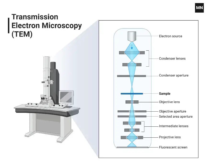
Parts of Transmission Electron Microscope (TEM)
A TEM consists of several important parts that have different functions in the imaging process.
Electron Gun– The Electron Gun produces a beam of electrons that serves to illuminate the microscope.
Vacuum System– The Vacuum System maintains a high vacuum environment inside the microscope so that the scattering of electrons by air molecules does not take place, thereby ensuring that the image taken will be clear and precise.
Electron Lenses– Electron lenses use electromagnetic fields to focus and steer the electron beam onto the specimen, which then magnifies the transmitted electrons to produce a clear image.
Specimen Stage– The specimen stage holds the ultra-thin specimen firmly in place, allowing for precise positioning and manipulation during the imaging process.
Apertures– Apertures control the convergence of the electron beam and limit aberrations by selecting specific electron trajectories, thereby improving both contrast and resolution of the image.
Detectors– Detectors capture electrons after they pass through the specimen, and an image is created. While old detectors are fluorescent screens and photographic film, new versions of transmission electron microscopes have electronic detectors that are charge-coupled devices (CCDs) or complementary metal-oxide-semiconductor cameras.
Control Systems– Control systems include the computers and software dedicated to directing the TEM in the performance of its functions, including beam alignment, focusing, and image acquisition.
Transmission Electron Microscope (TEM)
How does a Transmission Electron Microscope (TEM) work?
It is a very strong tool that allows scientists to see and study tiny samples at a really small level. Unlike the light microscopes, which mostly depend on visible light, TEMs use a stream of electrons to make very clear images. The way a TEM works can be divided into a few main steps.
First, there is an electron gun at the top of the TEM that produces a stream of electrons. The most common form of electron gun uses a tungsten filament that is heated to very high temperatures. This heating causes electrons to be emitted from the filament surface through a process called thermionic emission.
Then the emitted electrons are passed through several electromagnetic lenses. These are condenser lenses that conduct the electron beam to where it strikes the specimen and also control how wide and strong the beam is. The current in the condenser lenses can be manipulated by the operator to enhance the beam for a particular sample and the imaging conditions they desire.
A very focused electron beam then strikes the sample, that is prepared with great care and placed on a small metal grid. As the electrons pass through the sample, a few get scattered by the atoms in the material. How much scattering takes place depends upon several factors, such as thickness of the sample, its density, and atomic number. Regions that are thicker or contain elements with higher atomic numbers will scatter electrons more strongly.
Below the specimen, there are more electromagnetic lenses, which include the objective lenses and projector lenses. These lenses focus and make the transmitted electron beam larger. The objective lenses produce the first enlarged image of the specimen, and then the projector lenses enlarges that image to be used on the screen or a camera at the bottom of the TEM column. The magnification power of TEMs is pretty high, with advanced instruments able to enlarge images over one million times.
The entire path of the electrons from the gun to the camera must be in a very high vacuum for the TEM to work properly. A small amount of air can scatter the electrons and thus make the image worse. Thus, the column of the microscope is pumped up to vacuum levels that are only comparable to outer space.
Finally, the large electron beam strikes a fluorescent viewing screen, making it possible for the scientists to observe and record an image. Those areas of the specimen that scatter more electrons, or are thicker or denser, appear darker, while areas that allow more electrons to pass through are brighter. This makes the images seen under TEM typically black and white in contrast.
Methods used for Sample preparation for visualization by TEM
Sample preparation is the most important step in TEM for getting good-quality images and data. The method of preparation is dependent on the type of sample and the kind of information to be extracted. Some common techniques for TEM sample preparation are:
Fixation: Crosslinks proteins and lipids of biological specimens with chemicals like glutaraldehyde and osmium tetroxide, thereby stabilizing them.
Dehydration: Removes the water from biological specimens using a series of ethanol or acetone solutions so that there is no structural disruption when the images will be taken.
Embedding: Infuses dehydrated samples in resins such as epoxy or acrylic, which helps support ultrathin sectioning.
Sectioning: The ultrathin sections (50–70 nm) are prepared using an ultramicrotome with a diamond or glass knife by slicing embedded samples.
Staining: Uses heavy metals like uranyl acetate or lead citrate, which bind to parts of cells to increase contrast.
Cryofixation: Freezes samples quickly so their original state is preserved; typically used for delicate biological specimens.
Ion Milling: A focused ion beam makes material samples thinner so that electrons can pass through without causing stress.
Drop Casting: Deposes a diluted suspension of nanoparticles or fine powders onto the TEM grid and then allows evaporation of the solvent, which leaves a thin film suitable for imaging.
Step by step procedure;
Preparing samples for Transmission Electron Microscopy (TEM) is very important. It includes careful steps to make sure the samples are thin enough for electrons to pass through and do not have any unwanted marks. Here are the main steps for preparing samples for TEM viewing: Sample Preparation Steps
First Cutting/Sectioning- Start by cutting the bulk material into smaller pieces, which would be less than 100 µm thick. This can be done using various techniques, like a slow-speed diamond saw, ultrasonic cutter, or electro-discharge cutting. The aim here is to obtain a sample thickness of about 150-300 µm before further thinning.
Thinning the Sample- Grind and polish the sample to approximately 5-15 µm. This is a preparation step that exposes the sample for further processes on a relatively scratch-free surface2. During grinding, apply gentle pressure to avoid creating cracks or damage in the specimen.
Punching Discs- When the sheet is thin enough, punch out discs 3 mm wide. Be careful not to damage the edges since usually only the center part of the disc is used for looking at it.
Dimpling- Dimple grinds the punched disc to make an area 2 to 10 microns thick on some parts of the disc, leaving a shallow dimple or pit in its center, permitting electrons to move through. End
Final Polishing- For TEM imaging, final electron transparency is achieved using methods like jet polishing or ion beam milling. Ion beam milling is very effective since it removes material at a slow rate and does not damage the surface; therefore, this is a good surface to observe. Electrochemical etching can be used for conducting samples sometimes.
Mounting on Grids- Mount the electron-transparent discs onto TEM grids once prepared. These grids are generally made of materials like copper, and in most cases, are coated with something similar to carbon to improve conductivity and prevent charging during imaging
Cleaning and Coating- Clean the sample by removing residues that have been deposited by previous preparation steps. This is often done using solvents like chloroform or ethanol. Optionally: carbon coat a thin layer on the surface of the sample to prevent any kind of glow discharge during TEM imaging.
Applications of Transmission Electron Microscope (TEM)
Materials Science – TEM is used to look at the tiny structure, crystal form, and flaws in metals, ceramics, and polymers, helping to create better materials.
Nanotechnology – TEM helps to analyze nanoparticles, nanowires, and other small structures, giving us information about their shape and makeup.
Life Sciences – TEM is used to study the ultrastructure of cells, tissues, and viruses to better understand biological processes and mechanisms of disease.
Semiconductor Research – TEM studies the microstructure of semiconductor devices, which determines defects and the quality of fabrication, very important to the electronics industry.
Pharmaceuticals – TEM helps in characterizing drug compounds and delivery systems to ensure efficacy and safety in drug development.
Geology– TEM studies the small structures of minerals and rocks, and helps us understand how geological processes work and the history of how Earth was formed.
Forensic Analysis- TEM helps in examining forensic samples by studying small evidence under a microscope, which supports criminal investigations.
Advantages of Transmission Electron Microscope (TEM)
Very high resolution. Images from the TEM are quite sharp, showing atomic-level structure. Powerful magnification: Structures can be enlarged to a view exceeding one million times, resulting in detailed images of tiny features.
It is easy to study various features of the sample with the help of TEM by using different imaging modes, including dark/bright field and phase contrast.
Electron diffraction patterns from small areas can be obtained using TEM to give information about the crystallographic structure of materials.
High-quality images are produced by TEM that helps in detailed analysis.
Permanent Image Capture, TEM captures permanent images. These can be used as a record as well as further analysis.
Limitations of Transmission Electron Microscope (TEM)
Sample Preparation- The TEM needs samples to be very thin, usually less than 100 nanometers, to allow electrons to pass through. This can be time-consuming and can change the natural state of the sample.
Vacuum Environment- Samples must be placed in a high-vacuum environment so that air molecules do not scatter the electrons. This makes TEM unsuitable for observing living specimens.
Radiation Damage- The exposure to the electron beam holds the potential to harm delicate samples, including biological specimens and polymers, which could result in structural alterations during the imaging process.
Limited Field of View- The Transmission Electron Microscope offers a comparatively small field of view, which might not accurately reflect the entirety of the sample, thereby possibly introducing sampling bias.
Complex Image Interpretation- TEM images represent two-dimensional projections of three-dimensional structures, meaning that complex analysis and interpretation is required to make an accurate morphological understanding of the sample.
Instrumental Constraints- TEM instruments are large and expensive, which requires specialized facilities and maintenance and may limit the accessibility of TEM for some researchers.
A Scanning Electron Microscope is a game-changer in the world of imaging. Imagine the ability to zoom in on an object so closely that even the tiniest details come alive in stunning clarity. That is what SEM does. But how does it work? Let’s break it down.
An SEM uses a beam of electrons instead of light to look at the surface of a sample. The electrons work with the atoms in the sample to make signals that form an image. Unlike regular optical microscopes that use light, SEM can show much finer details—up to 100,000 times bigger! This means you could see the surface of a cell and even look at individual molecules. That’s pretty amazing, isn’t it?
What really makes the SEM special is the level of detail it provides. The electrons are traveling over the surface of the object and then bouncing back to make clear, 3D images. Think about studying a tiny bug: you’re not just going to see its legs but the fine texture of its shell in great depth and clarity.
The problem is there, though. The SEM can’t tell you what’s inside your specimens. It only shows you the surface. That’s an enormously valuable thing for researchers and scientists. Whether you’re studying materials, biological samples, checking for cracks in a metal surface, it gives you information you can’t get with a regular microscope.
It can be a great curiosity spark in the classroom or lab. Do you ever wonder what things look like at the molecular level? SEM lets you see them in fine detail. In fact, it has revolutionized fields such as material science, biology, and even archaeology!
Now, I don’t mean to mislead you—SEM is not something to take lightly. It is a special tool that needs careful use and specific ways to prepare samples. For instance, biological samples must be covered with a thin layer of metal, because electrons do not go through air easily. You can’t just place a sample under an SEM and hope for amazing results. It requires practice.
Even with difficulties, once you understand it, SEM imaging can be a very interesting way to look at tiny things. It’s like opening a door to a new way of seeing, showing hidden parts of reality that we couldn’t see before. It’s not just science; it’s science that feels amazing.
So, next time you’re studying materials or exploring the microscopic world, remember: the Scanning Electron Microscope isn’t just a tool, it’s a portal into a universe so small, it might just blow your mind!
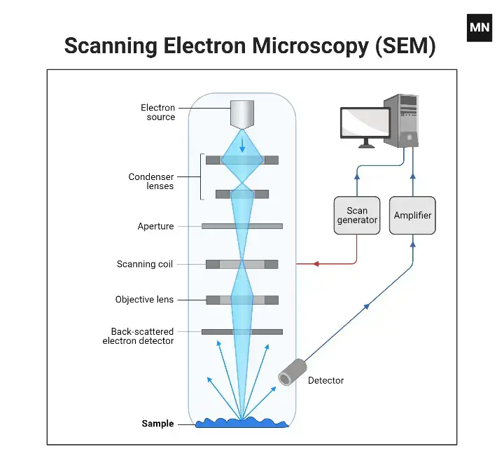
Definition of Scanning Electron Microscope (SEM)
SEM is a form of microscope which uses focused beams of electrons to view the surface of a sample. It produces very detailed images of the surface structure at a very high zoom level.
In 1937, Mafred von Ardenne built the first Scanning Electron Microscope to outperform the transmission electron Microscope. He scanned a small raster with high-resolution power, which was made using a beam of electrons focused on the raster. He also intended to reduce the problems of chromatic aberrations images produced by the Transmission electron Microscopes. Scientists and research institutions made more studies. One of the companies was the Cambridge Scientific Instrument Company. In 1965, they were able to make a whole Scanning Electron Microscope known as Stereoscan. A Scanning Electron Microscope cost around $1 million.
A Scanning Electron Microscope (SEM) is a kind of electron microscope that looks at the surfaces of tiny living things. It uses a low-energy beam of electrons to focus on and scan the samples. Electron microscopes were created because light microscopes were not very efficient. Electron microscopes have much shorter wavelengths than light microscopes, which gives them better ability to see details.
Principle of Scanning Electron Microscope (SEM)
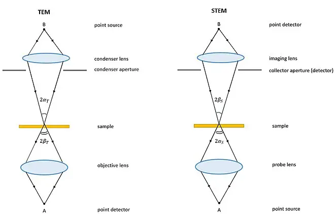
It functions by the collision of electrons and the surface of a sample to produce signals in the form of detailed images as well as information about the sample. In comparison, TEM takes advantage of the transmitted electrons while studying the sample. SEM studies the surface of the sample with the use of emitted electrons.
The focused electron beam will affect the specimen, leading to different types of electrons that come from the surface. They include secondary electrons, backscattered electrons, and diffracted backscattered electrons. Each of the emitted electrons contributes to forming the image.
The secondary electrons mainly allow us to see the shape and surface features of the material. Since they have low energy, they come from the top layers of the sample and provide us with minute information about the surface. On the other hand, the backscattered electrons, being more energetic, provide us with information about what the material is made of. The strength of the former is a function of the atomic number of the elements involved, helping to create differences in the final image.
In SEM, the electron beam travels in a grid pattern over the specimen. Upon hitting the surface, different signals are picked up and processed to create an image. This detailed imaging method enables researchers to view the small details of a specimen’s surface at a microscopic level, and it is, therefore, quite useful for material science, biological samples, and nanostructures.
So, SEM can create images of shapes, structures, and materials using electrons that it emits. It is a useful and important tool for scientific research.
How does the Scanning Electron Microscope (SEM) work?
Electron source and electromagnetic lenses – Tungsten filament lamps are used here as electron emitters. They stand at the top of the column similar to those being used in transmission electron microscopy. Electron emission – The thermal energy applied to the source causes the electrons to move rapidly toward the positively charged anode.
Interaction with the specimen– The electron beam generates primary (high energy) and secondary (low energy) electrons, which give information on the topography of the specimen’s surface and its composition.
Specimen treatment– Most samples, including air-dried ones, can be examined directly, but microbial specimens require fixation, dehydration, and drying to preserve structure and prevent collapse in the vacuum.
Sample preparation—The specimen is attached and coated with a thin layer of heavy metals to increase electron scattering and improve the resolution of the image.
Scanning process—The electron beam is scanned in a back-and-forth motion across the specimen. Secondary electrons are emitted from the surface of the specimen due to the interaction of the beam with it.
Secondary electron detection– The secondary electrons are trapped by a special detector where they hit a scintillator that produces light that is converted into an electric current to produce an image.
Image production– The current is transmitted to the cathode ray tube to create an image that is like a television picture, and can be viewed and photographed.
Surface contrast– The raised surfaces emit more secondary electrons, which appear brighter on the screen, while the depressed surfaces emit fewer electrons, which appear darker.
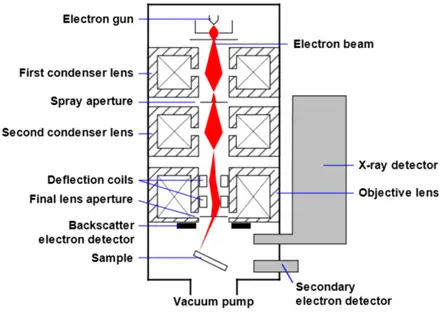
Mechanism of Scanning Electron Microscope| image
Parts of a Scanning Electron Microscope
The key components of a Scanning Electron Microscope (SEM) include:
Electron Source- This is essentially the source of electrons. These are generated using thermal heat and at a voltage of 1 to 40 kV. These electrons are gathered into a focused beam that is utilized afterward in imaging and analysis processes. There are three primary types of electron sources available for use: Tungsten filament, Lanthanum hexaboride, and the Field Emission Gun (FEG).
Lenses– The SEM has several condenser lenses that concentrate the electron beam emanating from the source through the column. This results in a narrow beam of electrons that gives a spot known as the “spot size.”
Scanning Coil- The scanning coil is used in deflecting the electron beam along the surface of the specimen, thus enabling scanning and imaging.
Detector– The detector system consists of several detectors which are capable of detecting secondary electrons, backscattered electrons, and diffracted backscattered electrons. Voltage speed and the specimen density may influence how well these detectors will perform.
Display Device (Data Output Devices)– The display device, or simply put, the output data device performs a very crucial role in data presentation associated with the scanning procedure. It facilitates in the visualization and analysis of the specimen.
Power Supply- This component provides the power necessary to supply the electrical energy that will run through all components within the scanning electron microscope.
Vacuum System- The vacuum system establishes and sustains a low-pressure environment within the SEM, which is crucial for optimal electron beam performance as well as avoiding interference with the imaging process.
Scanning Electron Microscope
Applications of the Scanning Electron Microscope (SEM)
Materials Science- They are widely applied to study surface morphology and composition of materials in the development and quality control of metals, polymers, ceramics, and composites.
Biology and Medicine- SEMs help in the study of cell structures, tissues, and microorganisms with respect to their morphology and their interactions. SEMs help identify diseases and viruses, test new vaccinations and medicines, and compare tissue samples of patients in the control and test groups.
Geology and Mineralogy- SEMs are used in the study of mineral composition, texture, and structure in order to gain knowledge on geologic formations and the discovery of natural resources.
Forensic Science- During forensic investigations, SEMs are used in the examination of gunshot residues and trace evidence including microscopic particles leading to criminal investigation and judicial processes.
Nanotechnology- SEMs are crucial for the development and characterization of nanomaterials, providing the ability to visualize and analyze structures at the nanolevel, an absolutely fundamental step toward applications of nanotechnology.
Advantages of the Scanning Electron Microscope (SEM)
High Resolution and Magnification- SEMs provide very high imaging resolution, which makes it possible to visualize surface details at the nanometer scale. This capability makes it possible to examine fine surface structures and microstructures with very high clarity.
Three-Dimensional Imaging- The large depth of field inherent to SEMs gives images a three-dimensional appearance and significantly enhances our perception of the topography of samples.
Elemental Analysis- The addition of EDS enables SEMs to perform qualitative and quantitative elemental analyses. This is an essential capability used in identifying material compositions and detecting foreign materials.
Versatility in Sample Analysis- SEMs can analyze a wide variety of sample types, including metals, polymers, ceramics, and biological specimens. This versatility makes them valuable across diverse research and industrial applications.
Non-Destructive Testing- The scanning process in SEMs is non-destructive, allowing for repeated analysis of the same sample without altering its structure. This is particularly advantageous in quality control and failure analysis.
Large depth of field– SEMs have a large depth of field so that more of the specimen is in focus at any one time. This feature is useful in studying specimens whose surfaces have various topographies.
Limitations of the Scanning Electron Microscope (SEM)
The costs of purchasing and maintaining SEMs are quite high. The intricate technology and various components lead to considerable initial expenses, and routine maintenance is crucial to uphold their peak performance.
Sample Preparation Requirements- Samples may be lightly coated with a conductive material, for example, gold or carbon to prevent charging under the electron beam. This is a laborious preparation procedure that also introduces artifacts unintentionally.
Vacuum Environment Limitations- Scanning Electron Microscopes operate in a vacuum, which may limit the type of samples that can be studied. For example, wet biological samples may require special preparation or are simply too wet to be imaged by SEM.
Risk of Sample Damage- The electron beam can damage sensitive samples, especially organic or biological samples. Electrons can catalyze chemical reactions, alter structures, deform, or even break samples.
Limited Information on Internal Structure- SEMs are mainly sensitive to the topography and chemistry at the surface of samples. Generally, they can offer very limited or no information about the structure inside unless a sample is prepared with careful sectioning. This may not be possible with all materials.
Size and Space Requirements- SEMs are large instruments that take up much space. Ideally, they are placed in an environment free of electrical, magnetic, or vibrational interference in order to maximize image quality.
Training and Expertise- The operation of an SEM demands thorough training in understanding the subtle nuances of the working of the machine and the basic principles of electron microscopy. It is crucial for high-quality images and avoiding damage to the microscope.
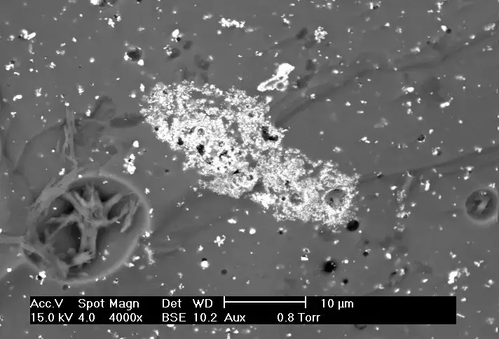
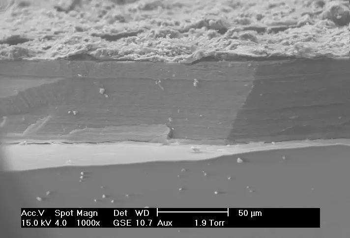
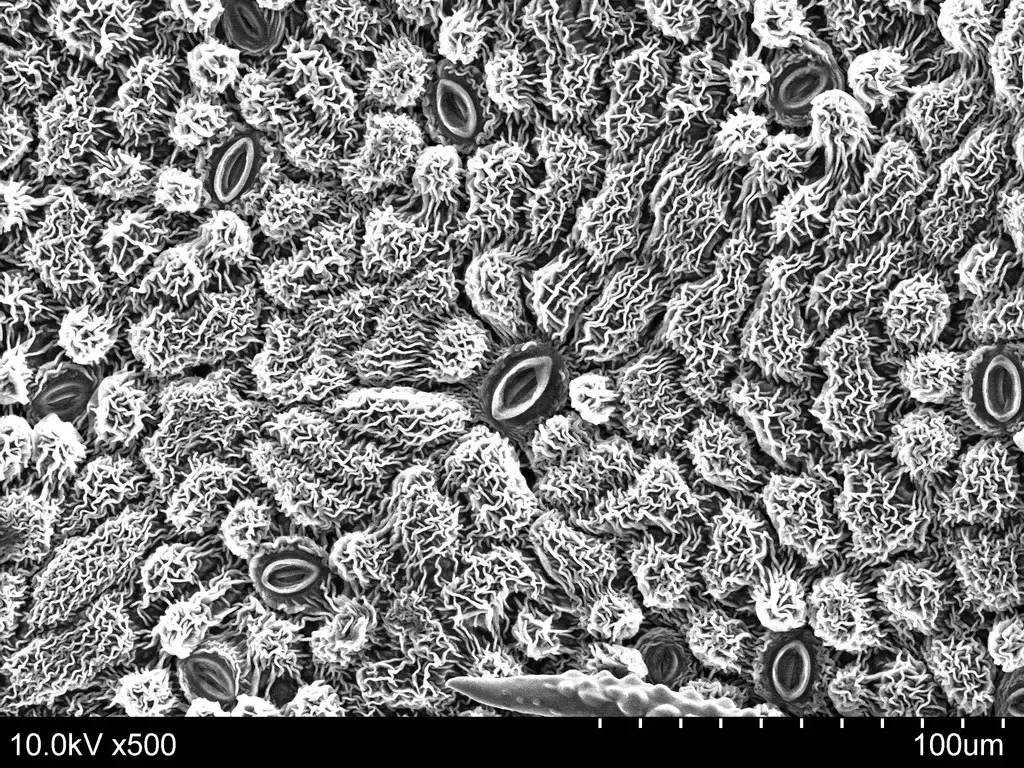
Scanning Electron Microscope (SEM) Images
Scanning Electron Microscope (SEM) Images – Colored SEM image of Tradescantia pollen and stamens | Image Source: wikipedia.org
Scanning Electron Microscope (SEM) Images – Backscattered electron (BSE) image of an antimony-rich region in a fragment of ancient glass. Museums use SEMs for studying valuable artifacts in a nondestructive manner.
Scanning Electron Microscope (SEM) Images – SEM image of the corrosion layer on the surface of an ancient glass fragment; note the laminar structure of the corrosion layer.
Scanning Electron Microscope (SEM) Images – SEM image of stomata on the lower surface of a leaf.
Phase-contrast microscopy transforms subtle variations in refractive index and cell density into noticeable changes in light intensity, allowing researchers to study living cells.
The microscope is a microscope for viewing cell culture and live cells. Living cells can be seen unstained.
Unstained specimens have absorbed no light, so it produces very small differences in the intensity distribution in the image. So in brightfield, the specimen cannot be viewed very well.
Due to a slight phase shift when light travels through specimens, which is invisible to our human eye.
Phase contrast microscopy then converts these phase shifts into alterations in amplitude, which are distinguishable as variations in image contrast.
The phase concept was discovered by the Dutch physicist Frits Zernike at the University of Groningen in 1932. He wrote of its use in microscopy in 1935. He received the Nobel Prize for physics in 1953 for that. With the use of a special filter in the condenser, Zernike filtered undiffracted light from the specimen from diffracted light from the specimen.
He used a special plate on the back focal plane of the objective lens and changed the phase of the direct light to make it up to 4 times out of phase with the diffracted light. The increased interference between the direct and the diffracted light in the intermediate image plane created visible amplitude contrast for the microscopist.
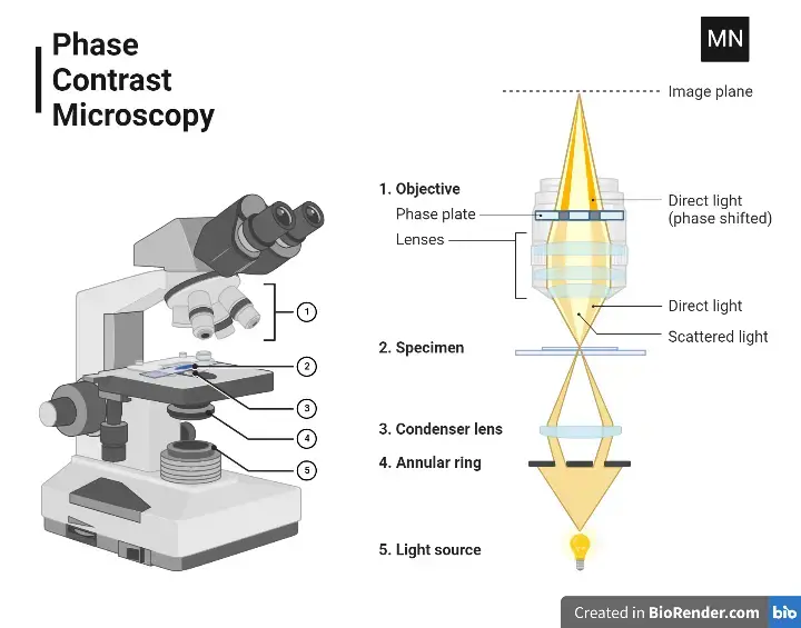
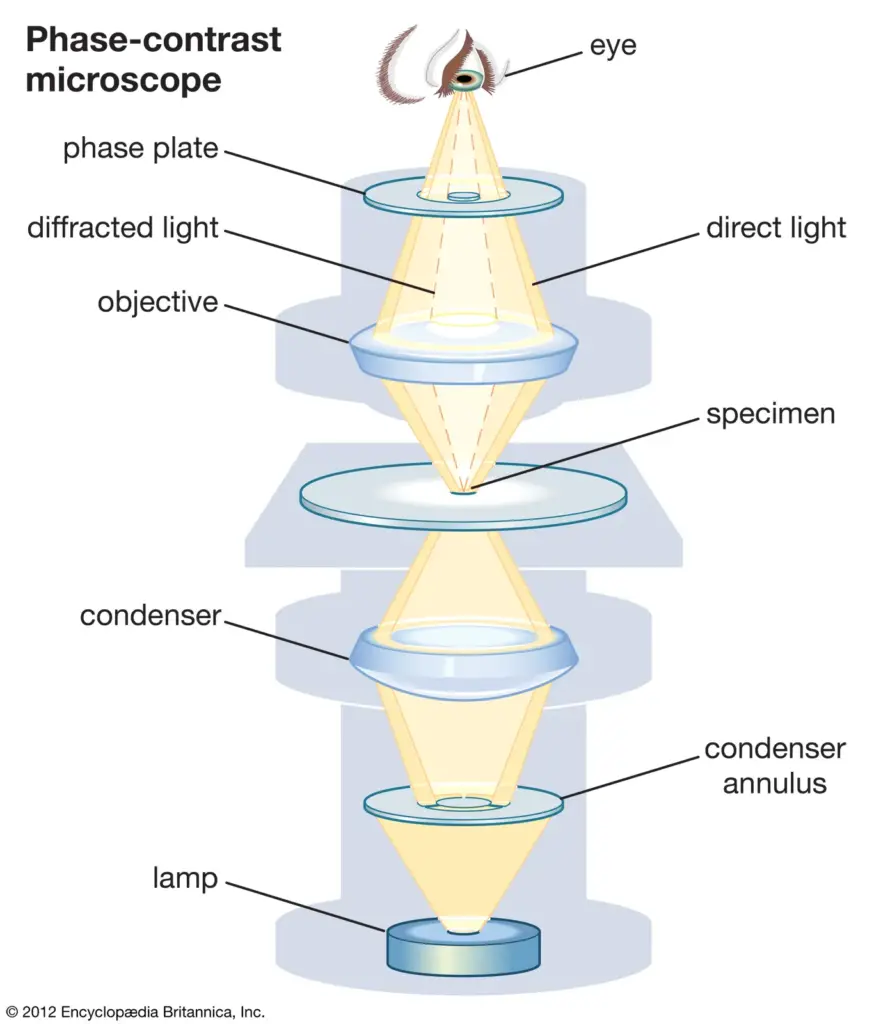
Principle of Phase contrast Microscopy
The condenser of a phase-contrast microscope is equipped with an annular stop, which is an opaque disk having a thin transparent ring that forms a cone of light with a hollow interior.
As part of this cone travels through a cell, some light rays are refracted because of the density and refractive index variations within the specimen and are therefore ‘retarded’ by a quarter wavelength. The deflected light is focused to create an image of the object.
The undeviated light rays strike a phase ring in the phase plate, a specialized optical disk located in the objective, while the deviated rays bypass the ring and pass through the remaining part of the plate. The undeviated light that hits the phase ring is advanced by 1/4 wavelength when passing through this ring.
The deviated and undeviated waves become a half wavelength to each other and will cancel each other out to come together to form an image. And so diverged and undiverged lights of separate image.
The background consists of undiffracted light and is bright; the object, being unstained, is dark and well defined.
Light Path of Phase Contrast Microscope
Light Path of Phase Contrast Microscopy
The light rays emit from the light source and are received by the annular diaphragm.
And then, it went through the condenser lens that concentrated the rays on the specimen.
Light is transmitted through the specimen and onto the objective lens, where an image of the specimen is formed.
When light is passed through the specimen, it becomes deviated and non-deviated light rays.
These rays of light deviate and thus avoid the phase ring above the objective lens.
While the undeviated light rays hit a phase plate. Consequently, deviated and undeviated rays created separate images.
While the stray light rays provided the background of the specimen’s image.
Types of Phase Contrast Microscope
There are essentially two kinds of phase contrast microscopes:
Brightfield phase contrast microscopes- In these instruments, a conventional brightfield illumination system is used wherein the sample is illuminated from above and viewed using eyepieces or a digital camera. In these microscopes, the phase contrast effect is generated by the use of a phase contrast condenser and objective lens strategically located between the light source and the sample.
Differential interference contrast (DIC) microscopes– The DIC microscopes work on a slightly different principle to obtain the phase contrast effect. It does not have any phase contrast condenser and objective lens; instead, a special polarized light source with a pair of compensating prisms does the job for producing the effect of phase contrast. DIC microscopes are most useful while viewing transparent specimens like cells and tissues as they offer an increased degree of contrast that may not be provided by a brightfield phase contrast microscope.
Operating Procedure of Phase Contrast Microscopy
Generally, the standard protocol for phase contrast microscopy is given by the following steps:
Sample preparation: Usually, the sample is arranged by placing it on a microscope slide and overlaying it with a thin layer of immersion oil or a coverslip. For taking full advantage of the enhancement of contrast brought about by the phase contrast illumination, the sample should be kept at its minimal thickness.
The microscope contains a phase contrast condenser along with an objective lens, integrated with a typical phase contrast illuminating source. Both the condenser and objective lens are optimized for maximum effect in phase contrast. Then the illuminator is switched on.
The fine focus knob is used with the light source off to adjust the microscope’s focus. This allows the operator to find the exact plane of focus for the specimen being examined.
Illumination of the specimen: The light source is switched on, and thus the specimen will be illuminated using phase contrast illumination. The specimen is then observed either through the eyepieces or through the digital camera, as the focus is fine-tuned with the fine focus control.
Analysis of the specimen: The operator is then able to examine the sample and gain an understanding of what it is and what it might be composed of. Photographing or filming the sample may also be useful in further analysis.
How does phase contrast microscopy help scientists to visualize difficult specimens?
how does phase contrast microscopy help scientists to visualize difficult specimens?
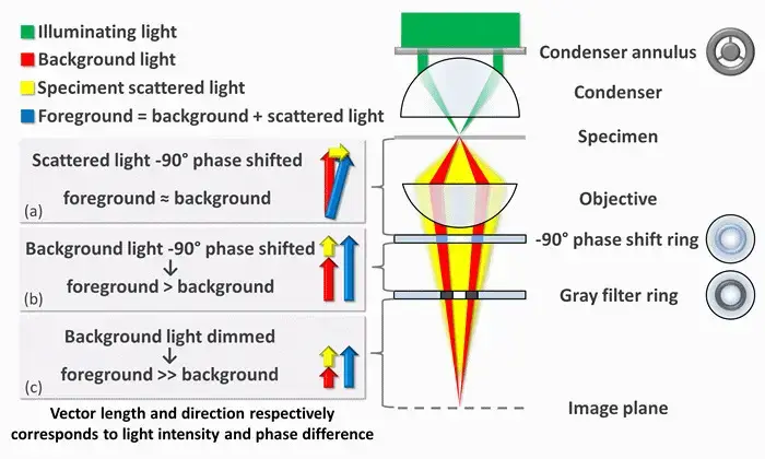
To make phase shifts visible in phase-contrast microscopy, it is required to separate the illuminating (background) light from the specimen-scattered (foreground) light and to modify them differently.
The ring-shaped illuminating light, which flows through the condenser annulus, is focused by the condenser onto the specimen. A portion of the illumination is scattered by the specimen (yellow). The remaining, undamaged light serves as background illumination (red). For light scattered from an unstained biological specimen, it is usually weakly phase-shifted by 90° with respect to the background light (since the typical thickness of the specimen and the refractive index mismatch between biological tissue and the surrounding medium). The intensities of the foreground (blue vector) and background (red vector) become therefore comparable, thus eliminating the picture contrast.
There are two main mechanisms for enhancing picture contrast in a phase-contrast microscope: creating constructive interference among the dispersed light rays and background illumination within the regions of the field of view that contain the specimen, and reducing the amount of background light that reaches the image plane. The first mechanism reduces the phase discrepancy between the scattered light and background beams by advancing the background light through a 90° phase-shift ring.
The change in phase causes constructive interference between the background and the scattered light coming from regions of the field of view that contain the sample; that is, the foreground. This causes them to be brighter than the other regions without the sample when light is focused to the image plane, where there is either a camera or an eyepiece.
Finally, the background is attenuated by 70-90 percent using a grey filter ring; such an approach improves the amount of scattered light generated by the illumination source but lowers the amount of illumination light reaching the image plane.
Only the phase-shift and the grey filter rings will receive some illumination from ambient light, with the dispersed light that bathes the entire surface of the filter being attenuated and phase-shifted to lesser extents.
The phenomenon described is a negative phase contrast. When inverted, the phase shift is +90 degrees, making the background light positive. The ambient light, therefore, will be out of phase by 180 degrees compared to the scattered light. In the next image, it is seen that the scattered light minus the background light produces an image where the foreground contrast is darker and the background lighter.
Parts of Phase Contrast Microscope
Phase-contrast Microscope
Phase Annulus in the Condenser: A black disc with a transparent ring that focuses light into a cone directed at the specimen. Meant to match the phase plates in the objectives, and comes with sizes appropriate for different objectives. Delivers partially coherent light, reduces optical noise, and aligns light with the phase plate.
Phase Plate in the Objective: A transparent plate with a circular ring – it may be loaded with materials that advance or delay phase. Changes the amplitude of light to produce positive or negative phase contrast, making dense organelles or features easier to view. Placed over the condenser’s phase annulus so that they are conjugate.
Phase Telescope: A type of eyepiece that transfers an image of the objective’s back focal plane to the observer’s retina. Placed to align the phase annulus with the phase ring, but sometimes an integrated Bertrand lens replaces it in microscopes.
Green Filter: Uses green light (525 nm) to optimize phase ring material for either phase advance or retard. While green is the traditional choice, white light can often be used successfully for phase contrast imaging.
Centering Tools: Tools to center the phase annulus in the condenser with the phase ring in the objective. Examined with a phase telescope to ensure good phase contrast imaging.
Eyepiece: The lens or set of lenses by which the observer views the specimen.
Head: Upper body containing the eyepiece, along with a structure that links to the objective
Arm: Structural component to hold the head and attach to the base of the microscope.
Base: A supporting foundation which provides the structure with stability, holding it steady.
Nosepiece: The rotating system attached to several objective lenses for easier change of magnification
Objective Lenses The actual primary magnifying lens located around the specimen for providing different magnification levels
Condenser Lens Directs the light from the source to the specimen for good illumination.
Specimen Stage This is the flat base on which the specimens are put, and usually contains clips to steady the slide on the stage
Stage Clips Holding devices, which support the slide while viewed on the stage
Aperture An opening in the stage that allows light passage from below to enlighten the specimen.
Applications of Phase contrast Microscopy
Cell Morphology-Phase contrast microscopy allows observing the fine detail and shape of living cells without using stains; thus, the views of cell organelles and membranes become quite different.
Live Cell Imaging– Live cell imaging allows the observation of living cells in their natural state, including monitoring cellular movement, division, and other dynamic processes.
Microbial Studies– It is used for the study of microbes such as bacteria and protozoa in their natural habitat and to enhance the contrast of transparent specimens without using dyes.
Tissue Analysis- useful for examination of thin tissue sections to bring out fine details and differentiation in medical and biological studies.
Neuroscience Research–Neuroscience research is used to view neurons in relation to their connections. This allows observing how brain cells and neural activity work.
Protein Localization– It helps in studying protein distribution inside cells and coupled with fluorescent markers, in understanding various cellular functions and pathology.
Advantages of Phase contrast Microscopy
Increased Contrast: Phase contrast microscopy is the technique through which the transparent and colorless specimens are viewed without staining.
Non-destructive Observation: The methodology allows us to observe living cells as they are, without needing fixation or staining.
Monitoring Real-time Process: Phase contrast microscopy permits us to study biological processes within the cell and tissues as it happens.
Cost-effective: Phase contrast microscopy does not need expensive dyes or stains, thus saving money for laboratory use.
Limitations of Phase contrast Microscopy
The primary limitations are as follows:
Halo Formation- The most serious problem is the appearance of halos around regions of high phase shift. Optical artifacts of this type mask the definition of details, which means that the fine structures of the specimen cannot be seen. Halos may be bright edges in positive phase contrast or dark edges in negative phase contrast and are difficult to interpret.
Reduced Resolution- The introduction of phase annuli in the optical system imposes a restriction on the numerical aperture, which in turn reduces the resolution of the images. This may be a particularly difficult constraint when high resolution is critical for the imaging experiment.
Distortion in Thick Specimens- Phase contrast microscopy is not as effective on thick specimens. The phase shifts that are induced from regions positioned above or below the focal plane can cause out-of-focus blur, thus causing distortion of the image and obscuring important details. This, therefore, makes obtaining clear images from thicker samples rather difficult.
Optical Phase Artifacts– Other optical artifacts could be expected besides halos, such as shade-off and contrast inversion. Shade-off refers to intensity gradients within large phase objects and therefore may give false interpretations in brightness and structure. Contrast inversion arises when a refractive-index high object’s brightness is larger than that predicted; hence the image interpretation becomes much more complicated.
Alignment and Light Intensity Requirements- Alignment of the light path is important in order for a successful phase contrast imaging. Also, this technique would usually need greater light than in bright-field microscopy because it employs dimming, not brightening.
Cost and Complexity- The addition of highly specialized components, including objective lenses and condensers employing phase contrast adds to the microscope’s expense and complexity. Its use in simple laboratories and, therefore in the schools is yet to be taken up.
The Confocal Microscope, like most advanced imaging systems, can be distinguished by its use of laser light to generate high-resolution images at varying depths within samples. These microscopes, which operate on the principle of confocal laser scanning microscopy (CLSM), then utilize a focused laser beam to scan specimens and detect fluorescence emissions at different depths.
It can be noted that the concept was initially developed by Marvin Minsky during the 1950s at Harvard University. The use of this technology, however, remained limited until sufficient light sources and computerised systems became available to manage the extensive data generated. Generally, the work was next adapted by David Egger M. and Mojmir Petran, who have developed a multiple-beam confocal microscope incorporating a Nipkow spinning disk – which they employed to examine unstained brain tissues and ganglion cells.
The use of confocal microscopy has expanded significantly across various fields. This includes biological research, medical investigations, and materials science, where they have become instrumental in studying cellular structures, tissue compositions, and molecular interactions at microscopic levels. Until the development of solid-state lasers and charge-coupled device (CCD) cameras occurred in the 1980s, the widespread adoption of this technology remained limited.
Like most significant technological advances, the modern confocal Microscope integrates various components. These include optical elements that perform the primary configuration function through electronic detectors, sophisticated computer systems, and laser arrangements. When a person can’t achieve high-resolution, three-dimensional imaging through conventional microscopy, they turn to confocal microscopy, which accomplishes this by scanning samples in sequential optical sections.
The first commercial confocal microscope emerged in 1987, equipped with enhanced optics, electronics, and high-efficiency scanning lasers. It is during the 1990s that the development of multi-photon excitation techniques and other advanced imaging methodologies further expanded the capabilities of these systems. They have since become essential tools for investigating molecules, microbial cells, and tissues at unprecedented levels of detail.
Principle of the Confocal Microscope
The Confocal microscope Uses point illumination as its principle working mechanism, unlike wide-field or Fluorescent Microscopes which illuminate the whole specimen, receiving complete excitement and emitting light detected by a photodetector. When a beam of light is focused at a particular point of a fluoro-chromatic specimen, it produces an illumination focused by the objective lens to a plane above the objectives- The objective has an aperture on the focal plane located above it, which primarily functions to block any stray light from reaching the specimen.
The illumination point measures about 0.25 to 0.8 um in diameter, determined by the objective numerical aperture and 0.5 to 1.5 um deep, with the brightest intensity. The specimen normally lies between the camera lens and the perfect point of focus, known as the plane of focus.
Using the laser from the microscope, the laser scans over a plane on the specimen (beam scanning0 or by moving the stage (stage scanning). A detector then will measure the illumination producing an image of the optical section. scanning several optical sections, they are collected in a computerized system as data, forming a 3D image which can be measured and quantified. Its outcome is also favoured by the aperture found above the objective which blocks stray light.
Images produced by the confocal microscope have a very good contract and resolution capacity despite the thickness of the specimen. Images are stored in the high-resolution 3D image of the cell complexes including their structures. The main characteristic of the Confocal Microscope is that it only detects what is focused and anything outside the focus point, appears black.
The image of the specimen is formed when the microscope scanner, scans the focused beam across a selected area with the control of two high-speed oscillating mirrors- Their movement is facilitated by galvanometer motors. One mirror moves the beam from left to right on the lateral X-axis while the second mirror translates the beam along the Y-axis. After a scan on the X-axis, the beam moves rapidly back to the starting point to start a new scan, a process known as flyback. No information is collected during the flyback process, therefore the point of focus, which is the area of interest is what is illuminated by the laser scanner.
Parts of the Confocal Microscope
The Confocal Laser Scanning Microscope is made up of a few key components –
Objective lens- This focuses the laser light on the specimen and collects the emitted fluorescent light.
Out-of-focus plane – This is the area above and below the focal plane that appears blurred in the image.
In-focus plane: The plane within the specimen that is in sharp focus.
Beam splitters – These are used to separate the excitation light from the emitted fluorescence light. They reflect the laser light onto the specimen and allow the emitted light to pass through to the detector.
Detector – It detects the emitted fluorescent light and converts it into an electrical signal that can be processed to form an image.
Confocal pinhole (aperture)- A small aperture placed in front of the detector that blocks out-of-focus light, allowing only in-focus light to reach the detector. This results in sharper, more detailed images.
Laser: Provides the excitation light for the fluorescent dyes in the specimen. Different lasers can be used for different dyes.
Oscillator Mirrors – These are used to scan the laser beam across the specimen in a raster pattern- One mirror moves the beam in the x-axis, while the other moves it in the y-axis, allowing the entire specimen to be scanned point by point.
Confocal Microscope
Types of Confocal Microscope
Confocal laser scanning Microscope – This type utilises several mirrors for scanning along X and Y axes on the specimen. Through scanning and descanning processes, the image then passes through a pinhole into the detector.
Spinning disk- Like most confocal variants, it can be identified as the Nipkow disk. These microscopes employ several movable apertures on a disc to scan for spots of light in a parallel manner over a specified plane. Generally, they have reduced excitation energy requirements compared to laser scanning types, which leads to decreased phototoxicity and photobleaching. It can be particularly useful when imaging live cells.
Dual spinning Disk (Microlens enhanced confocal Microscope)- Until Yokogawa electric developed this advancement, confocal imaging had certain limitations. The use of a second spinning disk with micro-lenses, positioned before the pinhole-containing spinning disk, revolutionised the process. When light passes through these micro-lenses, they capture a broadband of illumination, focusing it into each pinhole. This reduces blocked light at the spinning disk, making these microscopes significantly more sensitive than traditional spinning disks.
Programmable array Microscope (PAM) – The use of spatial light modulator (SLM) in these microscopes creates a distinctive imaging approach. They have movable apertures containing arrays of pixels with varying opacity, reflectivity, or optical rotation. It can be noted that microelectrochemical mirrors work in conjunction with a charge-coupled device (CCD) camera to capture images.
Mechanism of Confocal Microscope – How does a confocal microscope work?
Mechanism of Confocal Microscope – How does a confocal microscope work?
Confocal, with laser beams rather than lights. It emits laser beams that are concentrated on a fluorescently stained specimen.
Inserting neutral density filters and a set of scanning mirrors modulate the laser light: the mirrors move very precisely and rapidly.
One mirror deflects the beam in the X direction, the other in the Y direction. They work in unison to scan the beam in a raster fashion.
It is then focused by an objective lens onto the sample.
Once the fluorochrome labeled sample is excited, it will emit fluorescent lights.
These fluorescent lights will travel into the objective lens the reverse way that the laser travels, that is.
These scanning mirrors, their main effect on this light is to produce a non-scanning, but stationary, spot of light.
And then a semitransparent mirror deflects this fluorescent light away from the laser and into the detection system.
It goes through a pinhole before moving into the detection system. The pinhole only lets through the detectors in the center, a small part of the light.
Confocal microscopes emit very little light; therefore the light has to be amplified by a photomultiplier tube (PMT).
Photomultipliers can increase a weak signal by about one million times without adding any noise at all.
The PMT then sends out an electric signal, and a computer translates this into an image.
Excitation and emission light pathways in a basic confocal microscope configuration.
Applications of Confocal Microscope
Like most advanced imaging systems, the Confocal microscope can be utilized across diverse scientific domains.
In Biomedical sciences, it aids researchers when they need to analyse eye corneal infections – this is accomplished through the quantification and qualitative examination of corneal endothelial cells. These specialized cells, which can be murky and difficult to observe with conventional microscopes, become crystal clear under confocal examination.
Then there’s the microscope’s role in identifying fungal elements within the corneal stroma. This capability proves invaluable during keratomycosis infection, where rapid diagnosis is crucial for therapeutic response. It can be particularly effective when traditional diagnostic methods produce fuzzy or crowded images.
The use of Confocal microscopy extends into pharmaceutical industries, where they have found it essential for maintaining thin-film pharmaceuticals. This sophisticated tool ensures the quality control and uniformity of drug distribution with a precision ranging from 0.25 to 0.8 um – a level of detail that’s generally impossible to achieve with conventional microscopes.
These instruments have also revolutionised data retrieval from 3D optical storage systems. It can be noted that this application has proven particularly significant in quantifying the age of historical artifacts, such as the Magdalen’s papyrus. The microscope’s ability to produce detailed, layer-by-layer images at 45°C helps researchers examine ancient documents without causing degradation.
Through complex imaging techniques and fluorochrome technology, the Confocal microscope continues to advance research across multiple scientific disciplines. Like traditional microscopes, it serves as a fundamental tool in cellular Biology and genetics, whilst simultaneously pushing the boundaries in emerging fields such as Nanoscience and Quantum optics.
The Advantages of Confocal Microscope
This advanced microscope system can be distinguished by its remarkable capability to produce crystal-clear images. Like most sophisticated imaging devices, they have the unique ability to analyse specimens point-by-point, eliminating scattered light interference that generally clouds traditional microscopic views.
These microscopes excel in delivering superior resolution, where each focal point is meticulously visualized and captured. It can be particularly useful when examining both live and fixed cell specimens, offering a lot of ease in biological research. The use of confocal systems then allows for collecting serial optical sections, producing detailed cross-sectional views.
Generally, confocal microscopes ensure uniform illumination across focus points, which helps in producing clear, well-lit specimens. They have the ability to adjust their magnification electronically – without changing objectives – through what’s known as the zoom factor. This feature provides enhanced flexibility during specimen examination.
The microscope can generate impressive 3D sets of images, allowing researchers to visualize specimens from multiple angles. When a specimen needs to be examined thoroughly, these systems excel at producing detailed volumetric data that traditional microscopes cannot achieve.
It can be noted that the confocal microscope’s ability to eliminate out-of-focus light results in sharper images with better contract than conventional microscopes. The use of this technology has revolutionised the way researchers examine specimens, offering unprecedented clarity and precision in scientific imaging.
Limitationsof Confocal Microscope
This microscope system has only a limited number of wavelengths, which can definitely be a disadvantage when working with specimens that need multiple fluorescent markers and such markers. Like most high-tech instruments, they have limitations, which compromise their general usefulness in research.
Well, the expense can become a little troublesome. These things would cost a lot to make and even more to maintain. Labs don’t have money like that to pay it, usually.
Some are quite advanced, though still hitting the Resolution ceiling. It is a problem because when specimens become over 2 μm or so, images are difficult to obtain because too much fluorescence from specimens obscures detail.
The optical artifacts are a problem – the self-shadowing effects in thick specimens introduce much difficulty in image interpretation. Then the poor quality objective lenses cause spherical aberrations.
One should be aware that photobleaching is a significant limiting factor, where the fluorophores lose their ability to fluoresce if the imaging sessions last too long. And therefore compromises the quality of quantitative experiments and longer assays like cell imaging.
Due to the nature of the microscope and the image acquisition speeds, the. They have limitations, however, that are more evident during live cell imaging. And you cannot really observe real-time cellular processes.
Those systems have limited versatility because of the nonvarying pinhole sizes, and therefore imaging conditions and performances.
These finely tuned instruments only operate at a maximum utility level with thinner specimens (i.e., specimens greater than 2 micrometers have poor images).
Reference
Elliott AD. Confocal Microscopy: Principles and Modern Practices. Curr Protoc Cytom. 2020 Mar;92(1):e68. doi: 10.1002/cpcy.68. PMID: 31876974; PMCID: PMC6961134.
What is a Dissecting microscope (Stereo microscope)?
Dissecting microscope (stereo microscope), It’s typically used to look at small things or for dissections or soldering, activities that need close-up viewing.
Dissecting microscopes generally offer low magnification levels (approximately 4x to 50x) and have a relatively large working distance so that the object being viewed may be manipulated by hand using forceps or tweezers. Mainly biology, entomology, geology, and engineering use them.
A stereo microscope is composed of two eyepieces, each having its objective lens. These are affixed to a stand that is adjustable in both height and angle. The object that is being viewed lies on a stage that can be raised and lowered or moved around as desired to focus the image. Some dissecting scopes even come with a lamp or L.E.D.
This in turn led to the discovery of the dissecting microscope, first made in the 17th century with Anton Van Leeuwenhoek’s microscope of a simple single lens, a copia of which is on display in the R.O.M. But today’s stereo microscope did not arrive until the 19th century.
At the dawn of the 19th century, various scientists and inventors began experimenting with developing a microscope that would give the observer an actual three-dimensional image of the object. The English scientist William Brewster, one of the first to succeed, constructed a stereo microscope around 1827. Brewster’s design incorporated two lenses set on a single stand, and it was the first microscope to focus through both eyepieces, thereby producing three-dimensional images.
In the succeeding decades, numerous other companies and inventors have produced a variety of stereo microscopes. By the end of the 1800s and the beginning of the 1900s, stereoscopic microscopes were standard equipment in science and industry labs across the globe. Nowadays it is used in many different areas such as biology, engineering, and manufacturing.
Differences from normal optical microscopes
Some fundamental distinctions between a regular optical microscope and a dissecting microscope (also referred to as a stereo microscope), and some of the most significant similarities are:
Magnification: Standard optical microscopes usually boast a far greater magnification than dissecting microscopes. Conversely, dissecting microscopes usually have a magnification level between 4 and 50x.
Objective lenses: It usually has one or more objective lenses as to normal optical microscopes, whereas a dissecting microscope has two objective lenses (one for each eyepiece).
Working distance: Dissecting microscopes usually have a much greater working distance compared to regular optical microscopes, allowing the user to manipulate the object being viewed more adeptly with devices like forceps or tweezers.
Depth of field: The depth of field (i.e. the span of distances over which the image is in focus) is usually far greater in a dissecting microscope than in a conventional optical microscope. Seeing more of it at a time rather than on just one plane.
Image quality: Dissecting microscopes provide a more crude and less precise image than traditional optical microscopes because of the lower magnification of the dissecting microscope and the two separate optical tubes. Despite that, they are still good for looking at small stuff or stuff that would need that much magnifying detail to dissect it or solder it.
Principle of Dissecting microscope
In a dissecting microscope, both the objectives and the eyepieces have separate light paths, and these paths are critical for this microscope’s function. Every sunbeam brings a whole new idea. You can do dissections with the top light or look at slides with the bottom light.
Such light is illuminated in a binocular stereoscope, composed of two individual eyepieces, each displaying an artificial light path and each providing the viewing comfort zone. Digital microscopes provide real-time 3D display of specimens on a computer. Macro photography enables the enlargement of small things, such as (for example) insects, which would be too small to clearly view in a regular photograph.
For complex samples, the image is taken and the surface is looked at in 3-D. A dissecting microscope uses two types of magnification: fixed (primary) magnification and zoom (pancratic) magnification. In fixed magnification, the distance between the two objective lenses determines the magnification level. In zoom magnification, the auxiliary objectives provide a continuous magnification at varying levels; the purpose of these auxiliary objectives is to increase the total magnification.
By switching eyepiece lenses, the magnification can be either zoom or a constant. The Galilean optical system, positioned between fixed and zoom magnification, contains fixed-focus lenses which provide fixed magnification for different sets of magnifications, e.g., two sets of magnification give four-magnification, three sets give six-magnification, and so on.
Dissecting Microscope Parts (Parts of Stereo microscope)
LED Illuminators – The dissecting microscopes some have built-in lights such as a fixed LED illuminator.
Eyepieces- They each have a different pathway of light into and out of the specimen. Each one has its own degree of magnification. And to get greater magnification, you can add some auxiliary eyepieces.
Objective lenses: These also have different magnifications, focusing the image on the digital camera, and auxiliary objectives are employed to improve magnification.
Stage- This is the instrument used to position the sample. They are big, so they can hold large specimen equipment.
Optics System – anything between the fixed and zoom magnification that provides a fixed-focus lens.
Digital camera – it is temporarily mounted on most dissecting microscopes for taking pictures, and it records the result of the pictures. This technology takes both 2D and 3D images (if you have the 3D digital camera).
Dissecting Microscope Parts (Parts of Stereo microscope)
Types of Dissecting microscopes (Stereo microscope)
Dissecting or stereo microscopes are for looking at 3D objects. These instruments represent different varieties for different uses, unique characteristics, unique magnification abilities. The next few entries describe the major types of dissection microscopes.
Stereo Zoom Dissecting Microscope – This category has trinocular or binocular, zoom ration 6.7x to 45x. They could also have a digital camera to take images of the specimens they are viewing. A feature of these would be the double LED illuminator and the head that rotates 360°, which allows for extra viewing flexibility. You can adjust magnification by adding secondary objectives or eyepieces, which allows for more versatility for different jobs.
Digital Tablet Dissecting Microscope – These microscopes are a higher level – a touch-screen LCD tablet camera with continuous magnification zoom from 6.7x up to 45x. Auxiliary eyepieces permit changes in magnification—these are dialed into more detail by switching on additional lenses on the objectives. The built-in 5.0-megapixel digital camera enables image and video capture that can be saved directly to the tablet or downloaded via a USB cable connection. They have integral LED illuminators at the head and foot that work separately to provide perfect lighting.
Stereo Zoom Boom Stand Microscopes. – These have large bases and large platforms and can fit bigger specimens for examination. Their zooming range is from 6x to 45x, and can even go further by using auxiliary lenses or eyepieces. These microscopes use LED lights or dual pipe lighting so that adequate light strikes the specimen evenly.
Stereo Zoom Dissecting Microscope–The small version has a zoom of 10x to 30x and a crisp, parfocalled view. The revolving head allows the eyepiece to be rotated either toward or away from the object, increasing its utility. It’s illuminated with a 10-watt halogen bulb and a 5-watt fluorescent bulb, providing adequate lighting to see distinctly.
Dual Power Dissecting Microscope – With 10x and 30x magnifications, and a 360° rotating head, this microscope provides more observation flexibility. The second pair of objectives is parfocal, parcentered, and achromatic, so the image remains the same without any gray out. The lenses can be turned to change the amount of magnification. Also, an LED intensity light ring is used to illuminate the surface of the specimen evenly, and a flexible stand permits the viewing of larger objects at different heights.
Single Power Stereo Dissection Microscope- They have low magnifications of about 10x to 40x. These have inclined eyepieces at 45° and diopter adjustments for 50mm-70mm. All of these qualities lend themselves well to a job that demands less detailed observation.
Single Magnification Handheld Pocket Microscope- From Japan, portable microscope with two fixed magnification powers. There is no need for outside lighting, just straight-through high-quality optical glass. It is nice and small, so it is ideal for field work and just portable necessities in general.
Operating Procedure of Dissecting microscope
Like most microscopes that are used for examining larger specimens, the dissecting microscope (also known as stereoscopic microscope) can be utilised to study fossils, rocks, insects, and plant pieces, whilst they can also examine specimens mounted on slides.
The stages- These microscopes generally have two types of stages which can be used for viewing and dissecting:
The first type can be a black or white opaque stage – This design is widely employed when observing non-transparent specimens
Glass stage (transparent or opaque) – It can be used when illumination from below is required, particularly when the specimen is mounted on slides.
Installing the Stage- Before powering on the unit, the proper stage must be selected. When replacing an existing stage, these steps should be followed:
Loosen the stage plate lock screw to remove the current stage
When installing a glass stage, a blue filter is generally inserted into the stage’s central base
The stage can be secured by tightening the locking screw
Then reduce brightness to its lowest setting to protect the bulb’s life
Powering and Positioning- Next, activate the microscope using the on/off switch located on the base. The incident or transmitted light (or both depending on specimen) should then be activated. The body/head containing objectives must be lowered slowly using the coarse focus knob, which serves as a crucial foundation.
Eyepieces- The interpupillary distance needs adjustment by viewing through ocular lens and gently adjusting them inwards or outwards (similar to binoculars). Without a specimen present, a single circle should be visible through eyepieces after adjustment.
Specimen Mounting and focusing- The mounting process varies with specimen type:
For specimens like Hydra that require mounting on glass slides, both incident and transmitted light can be used
For opaque specimens (such as rocks), incident light is sufficient
After positioning the specimen in the focal plane, focusing can begin by gradually turning the focus knob until achieving sharp image clarity.
Zooming and Final steps- After initial focusing, the zoom knob can be used to examine specific areas with a lot of ease. When viewing structures like hydra tentacles, zooming may require additional focus adjustment as the image might become fuzzy.
The intensity controls allow for light emission adjustment and contrast modification.
At completion, these steps must be followed:
Return zoom to minimum level
Reduce light intensity
Power off using on/off switch
Cover with appropriate microscope cover/bag.
Applications of Dissecting microscope (Stereo microscope)
Like most microscopes that are utilised in various fields, the dissecting microscope (also known as stereoscopic microscope) has widespread applications across manufacturing, medical studies, quality control processes, inspection procedures and biomedical investigations.
These applications can be categorised into following areas-
Manufacturing and Quality Control-
Watch manufacturing processes that require high-powered magnification
Circuit board assembly and detailed inspection procedures
When quality checks need to be performed with a lot of ease.
Medical and Surgical Applications- This microscope can be utilised for:
Performing intricate microsurgical procedures where they need detailed visualization
Conducting dissections that require precise magnification power
Examining specimens under various zooming ranges.
Forensic and Engineering Studies- The use of stereo microscope includes:
Detailed inspection of fractures through fractography
Forensic engineering investigations where it can provide crucial details
Examining solid sample topography with enhanced clarity
Biomedical and Research Applications –
Entomological studies focusing on insect examination
Detailed specimen analysis that requires stereoscopic viewing
Generally employed when specimens need thorough inspection.
Quality Assessment- They have significant applications in:
Industrial inspection processes where quality is paramount
Examination procedures that need enhanced magnification.
Inspection Procedures- The microscope finds extensive use in:
Detailed component analysis
Manufacturing defect identification
Quality control processes that demand high precision viewing.
Research and Development-
Used extensively in biomedical research
Employed for detailed specimen examination
Applied in various scientific investigations
Advantages of Dissecting microscope
Like most microscopes that serve multiple purposes, the dissecting microscope (also known as stereoscopic microscope) possesses distinct advantages that make it one of the most significant microscopic techniques.
Versatility in Applications- These microscopes can be utilised across various fields, which makes them exceptionally valuable when different types of specimens need examination with a lot of ease.
Optical Advantages-
The use of dual light pathways offers enhanced magnification power
It can provide different zooming ranges for detailed visualization
They have superior image clarity through stereoscopic viewing.
Imaging capabilities- This microscope provides:
Digital camera attachment options for recording specimens
Enhanced documentation possibilities through imaging
Superior recording capabilities that aid in research
Practical Benefits – The stereoscopic microscope offers:
Easy portability that allows movement between locations
Simple operational procedures making it user-friendly
Convenient handling during specimen examination.
Specimen Viewing advantages –
Generally allows examination of complete specimens
It can view objects in their entirety rather than sections
The use of whole-specimen viewing provides comprehensive analysis
Operational Convenience- These microscopes provide:
Straightforward operational procedures
Enhanced ease of use during examination
Simplified handling for various applications
Technical Benefits-
Superior magnification capabilities through dual pathways
Enhanced image clarity for detailed examination
Comprehensive viewing options for various specimens.
Disadvantages of Dissecting microscope
Like most microscopes that have certain limitations, the dissecting microscope (also known as stereoscopic microscope) presents specific disadvantages that affect its functionality and accessibility.
Cost Implications-
The Galilean Optical Systems, which form an essential component, can be quite expensive
These microscopes generally require significant financial investment
It can be costly to acquire and maintain these systems.
Magnification Limitations- They have restricted capabilities including:
Limited zooming range that typically doesn’t exceed 100x
Reduced magnification power compared to other microscopes
The use of lower powered objectives restricts detailed viewing.
Structural Examination constraints- This microscope presents limitations when:
Examining minute tissue structures that require high magnification
Viewing specimens that need detailed cellular observation
Generally analysing structures requiring powerful magnification.
Technical Restrictions –
Limited capability for high-powered examination
Restricted usage for detailed cellular studies
The use is confined to lower magnification observations
System Limitations- These microscopes are restricted by:
Complex optical systems that increase procurement costs
Expensive components that affect accessibility
Limited application in high-magnification studies.
Practical Constraints-
Unable to provide detailed cellular examination
It can be restrictive for minute structure observation
Generally unsuitable for high-magnification requirements.
Dissecting Microscope Worksheet
Dissecting Microscope Worksheet
Dissecting microscope Sample images
Dissecting microscope images – Nematodes cultivated in different environments, as seen under a dissecting microscope. Images in the top row have a 500 m scale bar. Cultured nematodes, seen under a compound microscope (bottom row). The anterior of the worm is toward the top right in all photographs in the bottom row, and the scale bar is 50 m. Soil-grown C. elegans (A) and B. thuringiensis (B) lacking Cry5B in a well-culture setting. In the top row, not a single one of the six nematodes has been infected. Everyone here is perfectly fine. Some of the worms on the top row appear blurry because they are swimming around in the well. The pharynx and gut of C. elegans that have been fed B. thuringiensis without Cry5B are normal and unharmed (bottom row). B) C. elegans co-cultured with B. thuringiensis and Cry5B in a well environment. In the top row, five of the six worms are fully infected (they lack normal colouring and internal structures) whereas one is not. Infected animals in the bottom row have internal structures that have been completely or nearly completely digested by the bacteria. These fatally infected animals harbour both vegetative and sporulated forms of the bacterium. (C) Similar photos to (B), but this time Bacillus anthracis has been cultivated with the nematodes.
Dissecting microscope images – (A) Picture of a S aggregate under a dissecting microscope (A) on a white mat. The bar represents 1 mm on the scale. (B) Picture of S filaments on a white mat in phase contrast. The bar represents 10 m in actual size. A high-resolution scanning electron micrograph (SEM) image showing filaments and related cells in the white mat (C). Arc94-targeted cells, as seen in fluorescent in situ hybridization (FISH) image (D) (green). A photograph of flakes of iron oxide (Fe oxide) found in an orange carpet. The bar represents 1 mm on the scale. An orange flake as seen using a light microscope in (F). (G) A magnified SEM picture of a flake with broken sheaths. The arrows denote two types of hidden microorganisms (the bacteria themselves are not visible,
Dissecting microscope images – araignée poilue, 2 substacks de 21 images. Method=B (R=1,S=1) 90D sur stereo microscope
Types of Microscopes With Definitions, Principle, Uses, Labeled Diagrams
Picture yourself looking into a universe so small it cannot be seen by the eyes; microscopes open that galaxy. These clever gadgets make things and samples appear bigger, showing us a lot of complex, detailed stuff that wouldn’t be perceptible to us otherwise. Be it a scientist scoping out cells, or a student awing over the veins in a leaf, microscopes have a way of enlarging the microscope.
Through the centuries microscopes have changed from primitive forms to wondrous pieces of technology. Simple microscopes – one lens, good to use for observation of low magnification things. They are like the high-tech big brothers of the magnifying glass. And there are also compound microscopes–lots of lenses–that can magnify so precisely that it would make your eyes bleed. They’re the bread and butter of labs everywhere, whether it’s a biology classroom or a cutting-edge medical research lab. However, if you wish to delve into the very small—truly the small (microscopic)—electron microscopes are the big boys. Shooting beams of electrons instead of light, these marvels obtain a mind-blowing magnification with crazy detail. It’s sort of like they’re the superheroes of the microscopy world.
It is amazing to think though that it was only back in the late 16th century that we first got microscopes. At the time, they were like little refracting telescopes with a lens tossed in strictly for ornamental purposes. Skip forward a little and there is Antonie van Leeuwenhoek, a Dutch scientist who is the Sherlock Holmes of tiny objects. And his own-fashioned compound microscopes let him discover living cells, so he turned biology upside down like a snow globe. Think of the excitement of viewing what no human ever had before – life on a previously unimagined scale.
Innovation would reach supersonic speeds by the nineteenth century. Polarizing microscopes, phase-contrast microscopes, fluorescence microscopes – these new microscopes gave us a broader study of light and let us delve deeper into living and nonliving specimens. And these were tools that gave scientists vistas never before dreamed of. Then the electron microscope of the 20th century came, the so-called progressive of progressivos. Going from binoculars to a telescope to view the surface of the moon: instead of seeing 2 people having sex 20 miles away, now it is seeing 2 amoebas having sex 20 miles away—hmmm?
But to remind you, microscopes are not just microscopes. They have uncovered the unseen world of microorganisms, enlightened our understanding of cells and tissues, and made possible many of our technological and medical advancements. They are what allow us to understand the physical world. Otherwise, we would be reading a book without light. Therefore, the next time you see a microscope, go ahead and give it a knowing wink. It’s been laboring to render the invisible visible.
Microscopes
Types of microscopes
Microscopes have become specialized instruments, tailored to various requirements in research, education, and technology. The following is a summary of the primary kinds and their applications:
Simple Microscope – It’s a simple instrument, only one lens. It’s like a magnifying glass on crack—perfect for those low magnification jobs.
Compound Microscope – This one takes it to the next level with more lenses, offering greater magnification and better resolutions. Excellent for examining cells and tissues in the laboratory or classroom.
Phase Contrast Microscope – Have you ever tried looking at unstained cells? This microscope uses light phase shifts to enhance transparent specimens to achieve contrast without stains.
Fluorescence Microscope – Want to visualize fluorescent dyes or labels. This type involves using particular light wavelengths to highlight specific areas of a sample.
Electron Microscope – Substitutes electron beams for visible light. The result? Unrivaled in magnification and resolution with which to examine submicroscopic structures such as viruses.
Scanning electron microscope (SEM) – For producing beautiful 3D images by scanning a sample’s surface with electrons. Great study material.
Transmission electron microscope (TEM) – Can slice samples on the atomic scale. Perfect for those scientists investigating the intricate framework of the organelles.
Dark Field Microscope – Bright specimens on a dim background. It’s the basic observation for viewing live organisms or cells without staining.
Stereomicroscope (dissecting microscope) – Low magnification with a 3D view – ideal for dissection of organisms or examining minute objects.
Digital Microscope – Captures pictures and images digitally, usually with a computer monitor accompany. ‘Convenient for today’s labs and classrooms.
Scan Probe Microscope – It uses a mechanical probe to scan over surfaces and build up an atomic-level image. A necessity for the field of nanotechnology.
Atomic Force Microscope (AFM) – An SPM that detects surface interactions. Very suitable for the study of materials on the nano scale.
Inverted Microscope – It rotates the lens under the stage so you can look at samples in petri dishes. This is common in cell culture labs.
Acoustic Microscope – Images are produced of samples with sound waves. Useful in materials science and biology.
X-Ray Microscope – Employs X-rays, not light, for imaging – great way to view thick or dense materials, etc.
Polarizing Microscope – That is ideal for observing samples that are birefringent, such as crystals or minerals. Provides color contrast for thorough examination.
Metallurgical Microscope – Designed specifically to examine metals and alloys. You were heavily employed in quality control or failure analysis.
Pocket Microscope – Compact and portable. It comes in handy for field examinations.
USB Microscope – Then it plugs into your PC, and you can view it digitally. This is fine for hobbyists or just simple documentation.
Types of Microscopes
1. Simple Microscope
microscope simple drawing
Simple microscopes, or magnifiers, have only one double convex lens with a very short focal length. Instruments like the hand lens, or magnifying glass, are included here. It is a scientific rule that when something is close to the lens, an image is created. This image, unlike the image of the original object, is upright and magnified. Keep in mind that the picture generated will be virtual. But it’s not an image like one that can be put through a projector to a screen (it’s not that real).
Technically, the magnification of a simple microscope is given by the equation.
Magnifying Power=D/F
In this equation:
D is the closest distance the object can be seen clearly, otherwise known as the least distance of distinct vision.
F is the focal length of the double convex lens.
To sum up, the simple microscope is a basic optical device that provides a magnified beam of objects through its distinct lens arrangement. It is scientifically relevant because its magnifying power is dictated by a mathematical formula.
Working Principle of simple Microscope
When a specimen is placed at the focus of a microscope convex lens, a magnified, basically, virtual, image is found at the least distance of distinct vision. The components of a basic microscope include a mirror for illumination, a convex lens for magnifying, a stage, and a metallic stand with a base.
Applications of Simple Microscope
A lens is a basic tool of optics used with countless applications in science and technology. It’s the ability to magnify even the minutest of details makes it a compulsory tool in many domains. Here, we describe its main functions:
Morphological Studies – This led me to my second choice, the simple microscope, because without it, the morphology of so many different organisms could not be studied. It allows for close inspections of insects, algae, and fungi, so that they can be studied as to how they are structured and how they have adapted.
Pedologically – In the pedology domain, the single lens is used to determine the type of soil and the material within it. They are so important for studying soil capabilities, fertility, and its ability to support farming.
Micro-Device Repairs: All of the electronics tech classes use basic microscopes. The tools are a necessity when it comes to fixing things like watches, cell phones, and other intricate things. Their magnification ability guarantees their precision and accuracy in such meticulous tasks.
Gemological evaluations: jewelers use the basic microscope to determine the quality of precious gems such as diamonds. This tool permits an extremely close inspection of facets, inclusions, and all other little things that allow for the valuation of a gem.
Elaborate: Script and engraving interpretation Many historical manuscripts, engravings, or scripts have small letters that need magnification. In many such activities the simple microscope becomes an indispensable instrument, without which we would be blind to so much.
Advantages of Simple Microscope
Inexpensive – simple microscopes cost little.
Simple to use – Simple microscopes are simple to use, even for the microscopy novice.
Portability – Simple microscopes are compact and light, making it easy for you to carry them around.
Ideal for teaching – Simple microscopes are ideal for educational environments like schools, where students can be introduced to the basics of microscopy.
Disadvantages of Simple Microscope
Even though the basic microscope is rudimentary in its development of the optical field, it also has limitations. Like any scientific instrument, the limits of it as an instrument of scientific endeavor are precisely those within which it can best be utilized. We explain the main limitations of the simple microscope here:
Limited magnification – One of the most significant weaknesses of the simple microscope is its limited magnification. Usually its level of magnification is limited to about 10X. This kind of restriction usually prevents the close study of ultramicroscopic items.
Light and Stage – The simple microscope uses a mirror to provide light with. Unfortunately, this rather primitive method can, at times, yield less than desired lighting conditions on the viewed specimen. Moreover, the lack of a mechanical stage may create difficulties in moving and aligning the sample properly.
Requirements for Specimen – Specimens usually must be sliced extremely thin and stained properly to be seen clearly with a simple microscope. Such a requirement can be cumbersome and may simply be impossible for some samples, thus limiting the variety of samples which can be adequately viewed.
Resolution and Contrast – Resolution, the ability of a microscope to tell that two points very close together are separate, is quite poor in simple microscopes. This, combined with the problem of low-contrast images, can make it difficult for you to distinguish the details of specimens.
2. Compound Microscope
Compound Microscope Diagram
A compound microscope that uses visible light and a system of lenses to magnify specimens. The magnification goes up to 1000x; it is an important tool in microbiology, pathology, molecular biology, and life sciences. Its magnifying power: a function of its combination of an objective and an ocular lens:
m = D/f₀ × L/fₑ
m = magnifying power
D = least distance of distinct vision
L = tube length
fₑ = focal length of ocular lens
f₀ = focal length of objective lens
Working Principle
Condenser – focuses the light upon the specimen. This transmitted light is then taken by the objective lens and used to produce a magnified, real image through the body tube. This light is refracted and goes through the ocular lens to produce an even larger secondary image from the primary magnified one. The last image is appears at the nearest point of clear vision.
Parts of a Microscope
Illuminator (light source): Supplies the light needed to view the specimen.
Diaphragm (iris): Controls the size and amount of light in the beam.
Condenser: The purpose of the condenser is to concentrate the light on the object being viewed.
Condenser Focus Knob: Used to move the condenser in order to focus light.
Rack Stop – Limits how far upward the stage can move and thus prevents the objectives from breaking the slides.
Stage: Supports the specimen slide.
Stage Control Knobs: Move the slide left, right, up, and down.
Nose Piece: It rotates to change objectives.
Objective Lens: The objective lens offers the first point of magnification, and there are several objective lenses with varying magnification powers.
Tube (Head): It holds the ocular and objective lenses, maintaining the optical path.
Ocular (the eyepiece): It magnifies the intermediate image into the final image.
Diopter Adjustment: Diopter Adjustment lets the operator adjust the focus for slight variations in vision.
Adjustment Knobs:
Fine adjustment knob: adjusts focus on fine details.
Coarse adjustment knob function: provides movement of stage for primary focus.
Arm – This part of a microscope supports the body tube and can be used as a handle.
Base: Gives the microscope support.
Light switch/light dimmer: Light focus and control.
Applications
Microbiology – Morphology of Microorganisms.
Histopathology – study of tissue, cytopathic effects, and tumors.
Cytology – study of the cell structure.
Biology – Looking at cells, tissues, and biological parts.
Limitations
Will not work for anything smaller than the wavelength of visible light (~0.4 μm).
Even up against sophisticated imaging equipment, the resolution and contrast are limited.
It is not suitable for seeing inside living cells.
Specimens must be thin and stained to be visible.
Bright-field Microscope
In bright-field microscopy, it is the specimen which is dark and the background is light. Bright-field microscope: A light microscope that uses visible light and a system of lenses to magnify images of small samples. The light source is under the stage in a bright-field scope, so the sample is illuminated from the bottom. The light that travels through the clear or partially clear specimen is gathered by an objective lens passing it onwards to the eyepiece. This results in a light image against a black background, making it easy to view detail in the sample.
Bright-field Microscope
Light microscopes are the standard types of microscopes found everywhere; these bright-field microscopes. They are used frequently to study cells, tissues, and small structures of materials. A benefit of bright-field microscopy is that it is simple and straightforward to operate. Furthermore, it is relatively inexpensive when compared to other types of microscopes.
But bright-field microscopy is limited by many factors, including low distinction for transparent or non-colored specimens, and inability to differentiate things too closely packed together. Overcoming these limitations requires the use of another type of microscopy such as phase contrast microscopy or fluorescence microscopy.
Applications of Bright-field Microscope
These are used in the laboratory for studying the outer structure of microorganisms.
Advantages
Widely available: Bright-field microscopes are widely available and are often used in educational settings and laboratories.
Easy to use: A bright-field microscope is relatively simple to use, even for someone who is not very familiar with these machines.
Cheap: Bright field microscopes are relatively cheap in comparison to other microscopes.
Bright-field microscopy is suitable for opaque or semi-transparent samples: Bright-field microscopes are useful for examining opaque or semi-transparent samples, such as cells, tissues, and small features in materials.
Disadvantages:
Inadequate contrast for transparent or colorless samples: Bright field microscopy may not provide enough contrast for transparent or colorless samples such as bacteria or algae.
Lack of detail: Bright-field microscopy cannot resolve structures that are close together, so it has a lack of detail.
Few lighting options: In many cases, bright-field microscopes have a single light source, which may not be adequate for viewing certain samples.
Limited adjustments: Bright-field microscopes often have limited adjustments, such as the ability to focus or adjust the eyepieces, which may make it more difficult to obtain a clear image.
3. Phase Contrast Microscope
Phase Contrast Microscope is an optical instrument that translates minute phase shifts in light into differences in intensity, thereby producing high-contrast images. These changes take place as light shines through transparent specimens, which the human eye cannot see. Through the use of special optical components, these phase differences can be transformed into changes in brightness, which we can see as differences in the detail.
There is a special microscope, especially for seeing living cells and transparent structures without staining or fixing. Can be viewed in better contrast detail, including subcellular organelles, etc.
Phase-contrast Microscope
Working Principle
The light from the illuminator passes through a condenser annulus and is then focused onto the specimen. Because of differences in the specimen’s index of refraction and thickness, some light rays are phase retarded more than others. A phase plate placed in the optical pathway converts these phase shifts into amplitude shifts (contrast) in the final image. Regions with a higher index of refraction or greater thickness undergo a larger phase shift, resulting in more significant intensity variations.
Components of a Phase Contrast Microscope.
A phase contrast microscope has all the parts of a compound microscope along with two important optical components: the condenser annulus and the phase plate.
Condenser Annulus – Also called the phase condenser or sub-stage annular diaphragm. Below it, it directs a hollow cone of light upon the specimen. Built in the form of a black circular plate with a transparent annular groove, so that light can go through the annulus to light up the specimen.
Phase Plate – Located Over the rear focal plane of the objective lens. Could be split in two areas:
Conjugate area: Area corresponding to the light which passes through the condenser annulus.
Complementary Area: This is a complementary area. It has been painted with a light-retarding substance, for example, magnesium fluoride.
Alters the phase and/or amplitude of light leaving the sample.
Comes in two types:
Positive Phase Plate: Has a Thinner Conjugate Area.
Enhanced Phase Filter: Contains a conjugate zone that is thicker.
Applications
Viewing unstained living cells of live cells.
What are these bugs you ask, protozoa, diatoms, plankton, cysts, helminths, larvae, and everything else thought to be a contaminant agent.
Investigating subcellular structures and dynamics of cells.
Making tissue sectioning/scanning thin for histological analysis.
Lithographic patterns, latex particles, glass chunks, and crystals.
Limitations
Does not work well with thicker specimens because the light gets scattered.
Common issues like the halo effect and shade-off, which can obscure details.
Oh well, condenser annulus decreased aperture, thus the resolution decreases.
Phase Contrast Microscopy
4. Fluorescence Microscopy
Fluorescence microscopy is a type of microscope that uses fluorescence principles to analyze organic and/or inorganic samples. This is especially useful for looking at very distinct parts of cells or tissues that normal light microscopy renders difficult to see.
Fluorescent Microscope
How Fluorescence Microscopy Works
The basic premise of fluorescence microscopy is to (output volume) illuminate fluorescent molecules, termed ‘fluorophores,’ in a specimen. And the procedure can be simplified to a few important steps.
Sample preparation: Samples are tagged using fluorophores, which are compounds that absorb light of one wavelength and re-emit it at a longer wavelength.
Light Source: A very bright lamp, like a xenon arc lamp or mercury lamp, provides light to excite fluorophores in the specimen. Such light is usually in the UV or visible range.
Fluorescent Emission: The fluorophores give off light of longer wavelength (lower energy) after excitation. It is this emitted light that is detected and recorded to make the image.
Filtering: Specialized filters are used. These filters are selectively used to block all emitted fluorescent light, except for the fluorescence itself, so that only the fluorescence reaches the eye of the observer or the eye of a camera (an automatically recording light-detecting instrument).
Parts of a fluorescence microscope.
A fluorescence microscope has essential additional parts that distinguish it from ordinary optical microscopes.
Light Source: A strong lamp (e.g., xenon or mercury) that delivers the required excitation light.
Excitation Filter – this allows certain wavelengths to pass, which must correspond to the absorption spectrum of the fluorochrome in use.
Dichroic Mirror: Usually placed at a 45-degree angle, this mirror reflects the excitation light toward the specimen and transmits the emission fluorescence light to the detector.
Emission Filter: This filter allows only certain wavelengths of emitted light to get to the eye, thereby improving the image displayed by blocking out unwanted wavelengths.
Types of Fluorescence Microscope
Fluorescence microscopy is a specialized field of optical microscopy that includes several different types for specific uses in research and diagnostics. This differentiates the major categories of fluorescence microscopes and their traits:
Epifluorescence Microscope: A very common type of florescence microscope is the epifluorescence. The key to its property is that the excitation light path is the same as the emission light path- both go through the same objective.
Confocal Microscope: Also known as a confocal laser scanning microscope, uses a spatial pinhole to obstruct out-of-focus light, resulting in 3-D images with improved resolution and contrast. The microscope illuminates a spot on the focal plane with excitation light, which is then optically moved to scan the whole sample.
Process: Laser illuminates the specimen that is stained with the fluorophore. The resulting emitted fluorescent light travels through a pinhole which allows the light from the focus yet effectively eliminating the background light. That light is then converted into an electrical signal by a photomultiplier tube, and computer software interprets this signal and produces a 3-D image.
Applications:
Detection of corneal disease and presence of fungal elements from corneal scrapings? Detection of corneal disease and presence of fungal elements from corneal scrapings?
Pharmaceutical quality control analysis.
Optical 3D scanning and imaging.
Limitations:
Limited excitation wavelength and narrow bands.
High cost of the system.
Multiphoton Microscope: This type of microscope uses 2 or more photons to excite the fluorophore molecules, producing high-res 3D images. The most common types are two-photon and three-photon excitation microscopy.
Total internal reflection fluorescence (TIRF) microscope – The TIRF Microscope provides a very good image of fluorophore molecules in an aqueous medium near the surface of a high refractive index solid. This type of selective imaging produces images of exceedingly high clarity.
Pros: The TIRF microscope provides high-contrast, low-background, highly defined images, which is really useful for these particular imaging games.
Applications of Fluorescence Microscopy
Fluorescence microscopy, due to its ability to produce high-contrast, highly specific images, is an essential and prevalent tool in numerous scientific disciplines. Some of the more prominent applications are:
Cell Biology: Studying cellular structures and processes by labeling specific proteins or organelles with fluorescent dyes.
Microbiology: Capturing images of microorganisms in order to identify the species and determine their activities in the presence of certain conditions.
Biomedical research; studying the mechanisms of diseases by seeing how cells interact and how they change over time.
Environmental Science: Science mineral and biological sample analysis lab.
Advantages
High sensitivity: Able to detect relatively low concentrations of fluorophores.
Specificity: The ability to target specific molecules in complex samples by using custom fluorophores.
Fast Imaging: It allows simultaneous viewing of many fluorescent markers and hence fast analysis.
Limitations
Photobleaching: Fluorophores will bleach after prolonged exposure to intense light.
Depth penetration is the restricted capacity to visualize deeper tissues owing to the scattering and absorption of light.
Elaborate sample prep: Must pay close attention to sample labels and deal with the samples, which is usually tedious.
5. Dark-Field Microscope
One is the dark-field microscope, which is a modified light microscope, differing somewhat in illumination and the image. Below we explore the workings and uses of that sophisticated optical device.
Basic Design and Principle: The Dark-Field microscope utilizes a modified light source. At the heart of this system lies an opaque disk located under the condenser lens. This disc blocks the direct light from the source from entering the objective. Only the light on the specimen is detected. This means that the specimen is being lit laterally, from the side, at a low angle. The scattered light is gathered by the objective lens and then focused on the eyepiece to form an image in which the specimen appears bright against a dark background.
Dark-Field Microscope
Imaging Characteristics:
Enhanced contrast and resolution: The dark-field microscope reveals my images in increased contrast and resolution than bright-field microscopy. This is especially good for seeing small things in specimens.
Dark-Field Microscopy – Viewing Unstained Specimens: One of the greatest benefits of using dark-field microscopy is not having to stain the specimen. This helps you to view objects in their own natural form and texture.
The resulting images are bright specimens on a dark background.
Dark Field Microscope Uses
Microbiology:
Microbial Movement. The darkfield is good for something though; it makes it easier to see the movements of the little creatures. Their mobility fascinates me.
Spirochetes and thin bacteria: The method is particularly good at viewing very thin bacteria such as spirochetes, which are not easily seen using conventional microscopy.
Capsulated organisms: Organisms with capsules, or protective layers, around their cell walls. Dark-field microscopy would show the best results in obtaining details of organisms.
Cytology: Dark field microscopy is used in cytology, the study of cells. It is especially great when you want to look at the inside organelles and really get into what the cell is made up of and what it does.
Technological Uses: As far as technology goes, the dark-field microscopes have even been configured into computer mice. This makes the mouse perfectly usable on clear surfaces, thus increasing its flexibility and its overall applicability.
Characterization of Nanoparticles: However, when combined with hyperspectral imaging, dark-field microscopes are a powerful tool for nanoparticle characterization.
Dark-Field Microscope
Advantages of Dark-Field Microscope
The image has high contrast because this dark-field contrast can potentially show class fine details and structures that are not seen in bright-field microscopy.
Dark-field microscopy is especially suitable for transparent or semi-transparent samples, such as bacteria, algae, and small crystals.
It is able to see fine details and structures: Dark-field is capable of observing fine details and structures that are lost in bright-field, such as flagella and bacterial cells, or algal spines.
Disadvantages of Dark-Field Microscope
Reduced field of view: The field of view in dark-field is typically smaller than that in bright-field.
Cannot give a true color image: dark-field microscopy cannot give a true color image of the sample.
Needs experienced operator: Dark-field microscopy necessitates a very experienced operator to align the dark field microscope and illuminate the light source for it.
Few lighting choices: Often, dark-field microscopes only have one light, and some samples or areas just seem too dark.
Limited adjustments: Dark-field microscopes often have limited adjustments, such as the ability to focus or adjust the eyepieces, which may make it more difficult to obtain a clear image.
Difference between dark field and bright field Microscope
6. Electron Microscope
The Electron Microscope is a new form of microscope in which it uses accelerated electron beams as illumination instead of ordinary light rays like the opt, microscope. The following characteristics are the foundation upon which both the structure and operation of this instrument are based:
Electromagnetic Lenses: The Electron Microscopes employ electromagnets in lieu of glass lenses. These electromagnetic lenses serve the purpose of focusing and steering accelerated beams of electrons to provide accurate and clear imaging.
High-Resolution Imaging: One of the most significant benefits of the Electron Microscope is its capacity to capture images with incredibly high resolution. This is due to the naturally short wavelength of electrons that allow the observation of minute details not visible with optical microscopes.
Magnification Capabilities: The Electron Microscope can magnify specimens up to 10,000,000X. They possess the ability to magnify up to the nanoscale, showing things that have never been seen before by scientists.
Contrast and Detail: Apart from its resolution and magnification qualities, the Electron Microscope is very well known for its high contrast images. That guarantees that even the smallest of changes in specimen composition and structure are clearly visualized, giving researchers a full report of their samples.
Specimen Clarity: Its sophistication and technology allow specimens as small as 0.2 nm to be seen clearly. This ability is essential for experiments that require probing nanostructures and features.
Principle of Electron Microscope
Working on a different principle from that of the typical light microscope, the Electron Microscope is a state-of-the-art microscope. The basic idea and the working principle of the Electron Microscope are explained as follows:
Electron Generation: The electron gun, usually a heated tungsten filament or a field emission source, is the heart of the electron microscope. This part of the image creates a beam of electrons that are accelerated by using high voltage, the voltage is usually in the range of 100 kV up to 1000 kV.
Electron Acceleration and Focusing: Inside the microscope’s vacuum system, an anode plate accelerates the electrons. After this acceleration, the electron beam is precisely focused on the sample. This focusing is done through the use of multiple apertures and electromagnetic lenses to maintain accuracy in the electron trajectory.
Electron-Specimen Interaction: The accelerated electron beam strikes the sample, interacting with its constituents. This interaction causes electrons to scatter. Most importantly, this level of scattering depends on the specimen’s refractive index, thickness, etc. Regions or parts of the specimen deflect electrons to differing extents, giving rise to contrast in the final image.
Image Formation: Scattered electrons from the specimen are then captured and sent through several electromagnetic lenses, specifically objective and ocular. Both of these types of lenses are critical in bringing scattered electron beams into focus. These scattered beams are then picked up by magnetic lenses which convert them into greatly enlarged images. The naturally short wavelength of the electrons guarantees that these images show the very fine details of the sample.
Electron Microscope Parts
A highly advanced electron microscope, its components and structure guarantee optimal operational abilities. Below is a more detailed description of the main parts found in a common electron microscope.
The electron gun (electron source).
The electron gun is responsible for producing the electron beams necessary for illuminating the specimen.
It consists of a cathode (usually a tungsten filament) and an anode. When the tungsten filament in a vacuum is heated using high voltage, it gives off electrons. A negative circular cap surrounding these electrons acts to constrain the electrons into a small electron beam, and this beam is then accelerated by the positive anode to encounter the sample.
Electromagnetic Lenses:
Unlike optical microscopes that use glass lenses, electron microscopes depend on electromagnetic lenses, which use magnetic fields generated by electromagnets to focus and steer electron beams.
Types:
Condenser Lens: Focuses the accelerated electron beam onto the specimen, ensuring a precise and concentrated beam.
Objective Lens: Objective lens collects electron beams after they emerge from the specimen and magnifies it.
Projector (Ocular) Lens: magnifies the image formed by the objective lenses.
Aperture System:
These tiny holes filter out stray electrons from the electron beam, both before and after the beam strikes the specimen.
The system consists of thin disks with tiny pores from 2 to 100 μm. Important apertures are the condenser aperture (below condenser lens) and the objective aperture (between the objective and projector lenses).
Sample Holder:
The purpose of this device is a solid base with a mechanical arm to hold specimens in place.
Composition: It is usually an extremely thin carbon film mounted on a metal grid.
Vacuum System:
The vacuum creates an environment without air, allowing the easy creation of electrons and their free movement.
The lenses, aperture, sample holder, and specimens are kept in the vacuum column. To sustain such a vacuum difference, high-efficiency vacuum pumps are employed to avoid collision and scatter of electrons.
Imaging System:
The function of this machine is to digitize, enlarge, and display the images.
It consists of electromagnetic lenses, a phosphorescent screen for viewing the image, and a camera to capture and display the image. The resulting image, called an electron micrograph, is either projected onto a phosphorescent viewing plate or a television screen.
Application of Electron Microscope
Microbiology: Electron microscopes have a crucial function in microbiological research in that they allow scientists to see the ultra-structures of microbes. They are invaluable for deciphering the structural details of viruses, bacterial cells, flagella, and pili, to name a few, and consequently extending our knowledge of microbial physiology and pathogenesis.
Crystallography and Nanotechnology: In terms of crystallography, electron microscopy is employed to examine crystals in order to deduct the atomic configurations and lattice defects in the crystal structure. Moreover, since nanotechnology attempts to manipulate matter on the atomic or molecular level, electron microscopy gives them the picture so that they would be able to perform this precision surgery.
Cellular Biology: The shape of cell organelles such as mitochondria or the Golgi apparatus can be examined in detail with electron microscopes. This has been instrumental in the analysis of cellular function and malfunction.
Forensic Science: Forensics uses electron microscopy for ballistic analysis of gunshots. By studying gunshot residues and bullet fragments, investigators can obtain important evidence about weapons fired in criminal acts.
Geology: Geologists use electron microscopes to look at the microstructure of rocks, minerals, and gemstones. It helps understand how they were formed, what their past was, and how they have changed over the years.
Research and quality control in industry. In industry, electron microscopy is crucial, often as a quality control measure. It helps detect cracks, holes, and other kinds of flaws within materials. (Also in the pharmaceutical field, it assists in producing drugs since it allows researchers to observe the interactions of drugs with the molecular world and the analysis of atomic structures.)
Limitations of Electron Microscope
Electron microscopy is a powerful revolutionary imaging tool for scientists but it has its flaws. Those limitations come with the territory of the technology and they can be frustrating to the researcher and prevent them from using it in some situations. These are some of the major drawbacks of electron microscopy:
Economics and other possible complexities – The biggest problem with electron microscopes is that they are very expensive. It costs a lot of money to get these instruments and maintain them and use them. Because the system is so complex, people must be specially trained on how to use it. This creates even more expenses, and still further limits those who may benefit.
Monochromatic Imaging: Electron microscope images are in black and white. This lack of color can at times reduce the information available from the images, particularly when it is used to distinguish different parts or structures of a specimen.
TEM specimen thickness limitations. Transmission electron microscopy (TEM) requires very thin specimens, usually only a few nanometers thick. Specimens of such thickness are difficult to prepare and may be impossible for some samples. Additionally, this makes it impossible to get some information, such as that which could be obtained from thicker specimens.
Vacuum Requirement: Electron microscopes work in a vacuum so that the constant stream of electrons is not disturbed by air molecules. This uses an advanced vacuum system, which can be bulky (can = increased complexity. Moreover, the need for vacuum precludes the observation of living specimens and those that exist with water, possibly disturbing their native structures.
Types of Electron Microscope
Different kinds of electron microscopes exist today, such as:
1. Scanning Electron Microscope (SEM)
SEM stands for Scanning Electron Microscope. It is a type of electron microscope that has a different scheme to acquiring images and capabilities. This tool is very comprehensive in that it examines the surface of specimens and gives amazing three-dimensional images with a wealth of details. The basic description of the SEM, its structure, and characteristics are described below:
Scanning Electron Microscope (SEM)
Operational Mechanism:
The Scanning Electron Microscope (SEM) works by scanning a sample with a high-energy beam of electrons. Using this scanning pattern, it maps the surface of the specimen.
In contrast to the TEM (Transmission Electron Microscope), where the incident electron beam passes through the sample, in the SEM, the incident beam interacts with the specimen, resulting in electrons that are emitted, backscattered, or diffracted from the surface of the sample.
Image Formation:
The resulting images produced by the SEM (Scanning Electron Microscope) are 3-D and provide a topographical scan of the sample’s surface. These photographs graphically illustrate the morphological characteristics and the texture of the sample.
Though the SEM doesn’t give the magnification of the TEM, it has high resolution with better images. The result is clear, detailed images with a depth perspective that gives a true feel of what surface structures are like.
Detectors in SEM:
Central to the scanning electron microscope are its detectors, which detect different types of electrons providing more information and detail to the actual picture.
Backscattered electron detectors: detect electrons that have been backscattered by the specimen. Such electrons are generally a function of the atomic number of the sample and thus contain information about its composition.
Secondary Electron Detectors: These are sensitive to secondary electrons from the surface of the specimen energized by the incident electron beam. These electrons furnish insights into the specimen’s topography.
X-rays Detectors: These detectors measure levels of X-ray released from the specimen to determine elemental composition.
Application of Scanning Electron Microscope (SEM) – Used to study microorganisms’ surface areas in great detail.
2. Transmission Electron Microscope (TEM)
The transmission electron microscope (TEM) constitutes a specific type of electron microscope. Don’t get me wrong, it doesn’t work and take pictures in the same way, but it gives researchers the chance to look into the nanoscopic world like never before. The basic principle and characteristic of the TEM are thus clarified in the following:
Transmission Electron Microscope (TEM)
Principle of Operation: The TEM works by creating an enlarged image of a sample through the use of transmitted electrons. This is due to the passage of the electron beam interacting with the components of the specimen.
Specimen Thickness:
An absolutely fundamental characteristic of Transmission Electron Microscopy (TEM) imaging is that one needs to have very thin specimens. Such specimens generally are much less than 100 nm thick. To give you an idea, they are about 200 times thinner than those used in traditional compound microscopes.
Electron Interaction and Image Formation:
The combination of electron beam, focused onto the specimen by a condenser lens, interacts with parts of the specimen. After that, electrons are ejected from the sample. These electrons are then passed through a series of EM lenses, both objective and ocular lenses.
When these electrons strike the fluorescent screen, they cause the screen to fluoresce and form an enlarged image. This image production is the result of electron interaction with the screen, in which electrons strike and excite the screen to cause it to fluoresce, thus producing the image of the specimen.
Image Characteristics:
The TEM is well known for its two-dimensional images. They are black and white images but extremely high quality even though they are a single color. By their very nature, TEM images are of extremely high resolution, and indeed, this facility to visualize details on a molecular or atomic scale affirms this notion.
The TEM has a wide range of magnification from as low as 2X to 50,000X. This large range of magnification guarantees that scientists can adjust the imaging scale to fit their needs.
This is very common in scientific research: Of all electron electron microscopes, the TEM is by far the most common. It is commonly used in scientific research because it reveals small structures that cannot be resolved by optical microscopes.
Use of transmission electron microscope (TEM) – It is used to view the specimen’s internal structure.
3. Confocal Microscopy
Confocal microscopy, which is also called confocal laser scanning microscopy (CLSM) or laser confocal scanning microscopy (LCSM), stands as a revolutionary development in the field of optical microscopy.
Confocal Microscopy
Principle of Operation: Central to the functionality of confocal microscopy is the strategic use of a spatial pinhole. This pinhole is located at the focal plane and serves to block out-of-focus light in order to enhance the optical resolution of the obtained micrograph, as well as improve the contrast of the micrograph. Only in-focus light reaches the detector, which allows a sharply defined plane in the specimen to be scanned.
Three-Dimensional Imaging: Confocal microscopy offers many advantages, one of which is optical sectioning. The microscope allows you to take a series of two-dimensional images at different depths through the specimen in sequence, and then reconstruct the three-dimensional architecture that constitutes the internal structure of the sample. This is a great tool for learning about spatial relationships and the complex structures found in biological specimens, etc.
Advantages: The inherent characteristics of confocal microscopy’s architecture and manner of functioning make it preferable to conventional optical microscopy in several ways. In particular, improved resolution and contrast even result in three-dimensional images, and thus it is often used for larger objects such as cells and even organelles.
Application – Confocal microscopy is widely used in scientific and industrial circles, and common applications include life sciences, semiconductor review, and materials science.
There are different types of electron microscopes.
Boasting better resolution than any other form of microscopy, electron microscopy has since been derived into its own line of specialized microscopy. There are several electron microscopes other than the basics such as the TEM (Transmission Electron Microscope) that I was familiar with and the SEM (Scanning Electron Microscope) which introduce their own functions:
REM (reflective electron microscope) – Reflection Electron Microscopes use electrons that are reflected from or scattered from the surface of the specimen to form an image. This microscope employs various techniques such as diffraction, imaging, and spectroscopy.
STEM (Scanning Transmission Electron Microscope): The STEM is a combination microscope that uses both SEM and TEM technology. With these two types of microscopes utilized together, such as in STEM (Scanning Tunneling Electron Microscopy), almost any type of image can be produced, and surface and internal structures of a specimen can both be examined.
Scanning Tunneling Microscope (STM): The scanning tunneling microscope (STM) is the first technique developed that can image and manipulate individual atoms. Unlike other electron microscopes, the STM depends on the quantum mechanical effect of electron tunneling. The STM does not bore into the specimen; rather, it scans across the atoms and molecules on the specimen’s surface. The images generated are three-dimensional of these surface atoms and molecules. The STM, with its capability to image atomic-scale surface details, has become the biggest breakthrough for surface science with the visualization of atomic arrangements and molecular architecture.
7. Polarizing microscopes
A polarized light microscope is a specialized type of conventional light microscope that employs polarized light to illuminate the sample. Unlike conventional optical microscopes that utilize natural light, the polarizing microscope utilizes polarized light, which is light in which the vibrations of the light waves are sheared into a single plane. In other words, the main benefit of using polarized light is that it greatly improves the quality and contrast of the image. This improvement is especially useful for viewing samples that have a natural birefringent nature. The polarized light then passes through the sample interacting with these properties, resulting in unique and refined imagery. Polarizing microscopes, also known as petrographic microscopes, are very useful in geology and mineralogy. They are such useful tools for petrologists, allowing them to distinguish between the different minerals in thin sections of rocks.
Polarizing Microscope Principle
The basic principle of the polarizing microscope is the control of the beams of light that allow information from anisotropic objects to come through. Let me break it down for you:
Light source and polarization – The microscope begins by emitting standard light from its illuminator. This light is passed through a polarizer that converts it into plane-polarized light. Now the light waves oscillate mainly in one plane.
Interaction with the Specimen: The plane-polarized light is then passed into an anisotropic specimen. Anisotropic things have more than one refractive index, so they affect light in a special way.
Birefringence: When the plane-polarized light hits the anisotropic crystal, an occurrence referred to as birefringence takes place. This in turn leads to the separation of the light wave into an ordinary wave and an extraordinary wave. These waves are orthogonal, that is, they move in a manner that is perpendicular to each other.
Phase Transmission and Analysis: The two waves transmitted through the specimen are now shifted in phase because they have been retarded by differing amounts. Are then intercepted by an analyzer, a device very important in the polarizing microscope. The part of the analyzer is to merge these waves back together so that they can pass through the lens of the eye.
Image Formation: The end result of this process is a magnified, high-resolution image. The properties of the image are determined by how the specimen alters the polarized light, thereby allowing one to see things that would not be visible in normal light microscopy.
Polarizing Microscope Parts
The polarizing microscope is very similar to the normal light microscope, except that it has special adaptations used for polarized light microscopy. These parts are essential to the microscope’s ability to illuminate complexities of specimens. So here’s a closer look at these sections:
Polarizer: Located between the illuminator and the specimen stage, the polarizer is a key. It is a filter that makes light coming out of the light source which is unpolarized into plane-polarized light. This way, the light passing through the specimen vibrates mostly in only one plane.
Analyzer: Located in the light path above the objective lenses, the analyzer is the other key polarizing filter. Its main purpose is to rejoin the light waves once they have passed over the specimen. This recombination is essential to produce the final image that is seen.
Accessory Plates: Accessory plates, also known as compensators and retardation plates, are inserted before the analyzer in the optical path. They exist to measure the optical path difference or the relative retardation between the ordinary and extraordinary waves, caused by birefringence. They increase the contrast of the images so you can see inside the specimen better.
Specialized Stage: Unlike the fixed stages found in many standard microscopes, this microscope has a circular stage. This stage can spin 360°. This type of design also permits the very accurate alignment of the specimen to some special orientations required in a few polarized light microscopy methods.
Uses of Polarizing Microscope
The polarizing microscope has the special property of allowing polarized light to illuminate the specimen. This has applications in many different scientific areas. These are the main functions of this particular kind of microscope:
Of course, one of the main uses of the polarizing microscope is geological studies. This microscope is used by geologists to carefully observe and document different geological samples. The accurate study of the rocks, minerals, and everything that makes up soil. By the polarizing microscope, the crystal forms, mineral content, etc., appearing in these thin sections are revealed.
In addition to geology, the polarizing microscope has valuable applications in biology. Especially for a clear biological object. It helps in the analysis of planktons, diatoms, protozoans, etc., for example. When using polarized light, the internal structures of these organisms, which may be hidden by ordinary microscopic imaging, are brought to life.
Limitations of Polarizing Microscope
Though it has unique advantages in some scientific fields, the polarizing microscope is not total perfection. Such limitations are a result of its nature and its functional mechanism and are as follows:
The polarizing microscope has a major drawback in that it requires an anisotropic specimen. If the crystal is anisotropic, it will not have the same properties in all directions, which is what the microscope needs for the desired birefringent effect. Therefore, isotropic materials, which have the same properties in all directions, cannot be observed through a polarizing microscope. This limitation constrains the spectrum of samples that can be usefully examined by this method.
It has its drawbacks, though, such as the restriction of its use like the polarizing scope is a little too specialized. It is excellent for geology and some biology studies, but overall, it doesn’t seem to be a good tool of science. Its main utility is to those places where birefringence or the properties of anisotropic materials are of utmost concern.
8. Scanning Probe Microscope
SPMs create images with nanometer resolution that allows many properties of little structures and surfaces to be investigated. There are many different kinds of SPMs. For instance, there are Atomic Force Microscopes (AFMs), Scanning Tunneling Microscopes (STMs), and Scanning Near-Field Optical Microscopes (SNOMs). These devices operate by employing a probe that interacts in several methods with a sample: a probe that physically touches a sample and measures the force between them, a probe that is close enough for electrons to tunnel through the gap to the sample, and a probe that determines the near-field optical properties of a sample.
The use of SPMs helps in analyzing the surface properties of samples in several disciplines, such as materials science, biology, and nanotechnology, and aids in the examination of the composition and structure of these relatively small structures. (The sentence is not well written). They also are used to fabricate and manipulate small structures, for instance nanowires and nanotubes, and to characterize the properties of individual atoms and molecules.
The principle of the Scanning Probe Microscope.
In a scanning probe microscope, the probe tip is mounted on the end of a cantilever. The tip is so pointy that it is able to scan every single atom, moving exactly and exactly over the surface of the sample. Its tip is placed very near the surface of the sample, which gives rise to forces deflecting the cantilever. The laser measures how far in distance the deflection is. And after scanning, the end picture ends up on a computer.
Scanning probe microscope types.
Some of the various types of SPM (scanning probe microscope) use. Some of the SPM types include:
Atomic Force Microscopes (AFMs): AFMs utilize a sharp, cantilevered probe to measure the forces between the probe and the sample as the probe is scanned across the surface. The probe is usually a very hard and stiffer material (like silicon) mounted on a piezoelectric element that shifts the probe in very small intervals. Atomic force microscopy can be used not only to measure the topography of a sample but also to measure electrical, mechanical, and magnetic characteristics.
Scanning Tunneling Microscopes (STMs): Tunneling current is measured between the probe and sample as the very sharp probe is scanned across the surface. The probe is usually some metallic object, like tungsten, for instance, mounted on some sort of piezoelectric element that moves the probe in very nice small increments. Especially in the sense of measuring the topography of a sample and investigating the electronic properties of surfaces.
Scanning near-field optical microscopes (SNOMs): SNOMs scan a metal tip (such as gold) across a sample and analyze the optical near-field properties of the sample. The probe is usually attached to a piezoelectric element that steps the probe very small paces. What can be used to examine various samples’ absorption or scattering of light in SNOMs?
Scanning Capacitance Microscopes (SCMs): SCMs use a probe with a sharp tip to measure the capacitance between the probe and the sample as the probe is scanned across the surface. The probe is usually some metal glued to a piece of piezoelectric material that steps the probe in extremely small amounts. SCMs can measure the sample topography as well as electric properties.
Kelvin probe force microscopy (SKPMs): SKPMs utilize a probe with a sharp tip to measure the electrostatic potential of a sample when the probe is scanned over the surface. The probe is usually metal and is attached to a piezoelectric crystal that cause the probe to move in small steps. The KPFM can look at the topography of a sample as well as its electrical nature.
Application of SPM
To test different aspects of a sample, such as its electrical properties.
This microscope is used to analyze the magnetic property of the specimen.
Using this microscope, it is possible to transfer sample information.
9. Dissecting microscope (stereo microscope)
The Dissecting Microscope, otherwise known as the Stereo Microscope, is a special type of light microscope. The dissecting light microscope uses the principle of REFLECTED light microscopy, in contrast to traditional microscopes which use transmitted light through specimens.
Instead, the central operating principle of the dissecting microscope involves the reflection of light from the surface of the specimen. The reflected light is collected by the microscope’s optics and forms a magnified image. The design and optics of the dissecting microscope are such that they allow the specimen to be seen in three dimensions. Unlike most other light microscopes, which are used for viewing thin two-dimensional objects mounted on slides.
The dissecting microscope, as its name implies, is a great device for dissecting biology specimens. It gives researchers and students an accurate, larger-than-life view of their specimen, so they can work better. Apart from dissections, the 3D objects that the stereo microscope allows us to see make it an all-purpose instrument so that people can use it for something like taking samples of minerals in geology or in technology to examine something like electronics.
Principle of Stereo Microscope
A dissecting microscope, or stereo microscope, works based on a different optical principle from that of a compound microscope. By its very nature, the stereo microscope is built to give a 3D view of the object being observed.
Optical Principle: The basic concept behind the stereo microscope is its two separate optical paths. The difference being that in a typical microscope there is only one pathway of light, and in a stereoscope there are two, one for each ocular lens. This is the splitting of the path of light, which allows for a stereoscopic or three-dimensional image to be created. OK, the two eyes each focus on the specimen from a slightly different angle and each receive two slightly different images. When viewed together, these converge and create depth perception, which enables visualization of the 3-D structure of the specimen.
Illumination System: It is a stereo microscope that has an incident (reflecting) light and transmitted light (or a condenser). The upper light, known as incident light, shines on the surface of the specimen and is especially beneficial when dissecting or working with opaque specimens. On the other hand, the light from the bottom or transmitted light passes through the specimen making it easier to see clear or semi-clear specimens.
Objective Lenses, Stage. The stereo microscope’s objectives are enclosed in a cylindrical cone, rather than having exposed objectives like a compound microscope. It shields the lenses and also accommodates the microscope’s unusual optical arrangement. With the variety of specimens to be examined, the stage of the stereo microscope tends to be bigger than that of a compound microscope. One thing that is interesting is the groove or means of holding the specimen in place while viewing.
Applications of Stereo Microscope
Biological Procedures:
Dissection and microsurgery: The stereomicroscope is highly useful in biological laboratories during dissection. The capability to produce a three-dimensional perspective permits detailed exploration and manipulation of small organism samples, tissues, and organs. It is also used in microsurgery, where precision and depth perception are crucial.
Archaeology and Geology Study: The microscope is commonly used in archaeology and geology. Archaeologists use it to inspect and check artifacts so that nothing, no matter how small, escapes notice. Likewise, geologists use the stereo microscope to view rock samples, minerals, and other geological specimens, determining information about their composition, structure, and history.
Electronics and Precision Engineering:
Nano electric appliance manufacturing and welding or repair: With the complexity of electronics today from microchips to circuit boards, tools are needed that provide precision and revealing capabilities. The use of stereo microscopes is essential for the manufacture, inspection, and repair of such a component. Its capability to be magnified and seen in 3D guarantees that the smallest of parts get placed, soldered, or repaired correctly.
Watch Making: The horological world of watchmaking demands close attention and a delicate wrist. The stereo microscope helps watchmakers put together the small parts of the action of a watch, making the watch work accurately and dependably.
Mobile Phone Repair – With today’s cell phones becoming more technologically advanced, to repair any problem, you need a tool that is going to vividly display the fine workings of their innards. I envisioned the stereo microscope as a means to observe and mend the tiniest aspects of cell phones: circuitry, perhaps connectors.
Limitations of Dissecting Microscope or Stereo Microscope
Dissecting microscopes or stereo microscopes have many disadvantages.
Limited Applicability: Now, the stereo microscope is essential in that it can only be used for very specific things that need the person to see depth or something with three dimensions. Not the instrument of choice for higher magnification and the examination of cellular and subcellular structures.
Magnification Constraints: One of the main limitations of the stereo microscope is that it does not have very good magnification power. The magnification for a stereo microscope is not as great as that of a compound microscope or an electron microscope, as the stereo microscope cannot magnify a specimen as much as the other types. That limitation precludes, however, use of the method in examining ultra-subtle detail, structure on the cellular or molecular level.
Economic Considerations: Stereo microscopes, particularly high-magnification ones with various capabilities, can be costly investments.
10. Inverted Microscopes
As its name implies, the Inverted Microscope is an ‘upside down’ adaptation from a typical light microscope, with inverted positions of its primary features. Such a type of specialized microscope can serve better for some observations than others.
Design and Configuration: The main difference of the inverted microscope mainly has to do with that configuration. An inverted microscope basically turns the traditional upright microscope upside down; in a traditional microscope, your light source and condenser are below the specimen and your objective lenses are above. The objective lenses and turret are located below the stage and the illuminator and condenser are at the top of it. This in turn requires that viewers look up at the image to imagine the specimen.
Operational Principle: the Inverted Microscope basically functions the same way as an upright microscope. What it does is exploit the behavior of light to enlarge and clarify the details of samples. Yet the inverted design serves some special observational situations, especially in use with larger containers in which a sample is to be inspected and culture dishes in the examination of living cells.
Instrumentation: The primary elements of the inverted microscope are the same as in normal microscopes; however, the configuration is a defining factor of this type of microscope. It is inverted, so the light source, which is usually at the bottom in standard microscopes, is at the top in the inverted one. On the other hand, the Inverted Microscope has a turret and objective lenses, typically found above the stage in upright microscopes, that are positioned under the stage. Enabling a direct approach to the specimen, especially for large or unusual containers.
Digital Enhancements: So many of today’s Inverted Microscopes are accompanied by a digital camera to assist them by technology. These cameras allow them to take very nice pictures or movies of their specimens for analysis, documentation, and later distribution of the results.
Uses of Inverted Microscope
Metallurgical – In the field of metallurgy, the Inverted Microscope is an essential piece of equipment. It is used to examine the microscopic structure of metals and minerals. When these samples are lit from the top as the researchers look at them from below, they can help determine the grain structure, phase distribution, and other microstructural characteristics of metal samples. It plays a central role in the study of its properties and performance, enabling the creation of new alloys and enhancing the ones present.
Cytological Studies – The study of cells, known as cytology, also relies on the advantages of the inverted microscope. This tool is used by researchers to watch the cells divide, watching the steps of mitosis/meiosis as they are occurring on the cellular level. This type of microscope is specifically good for observation of cultures in Petri dishes because the specimen is unrestricted from above.
Microbiological Investigations: the inverted microscope comes in handy with certain organisms. For example, it is used to detect M. Tuberculosis, the organism that causes tuberculosis. Moreover, it allows for the possibility of seeing what certain pathogens like Phytophthora spp. look like when grown in culture. The Inverted Microscope provides a clear glimpse of these microorganisms to describe their morphology, life cycle, and interaction within their environment.
Limitations of Inverted Microscope
Limited Availability and High Cost: Even more, the knowledge of how an inverted microscope is constrained by the disadvantage that it is not available in many research facilities and even if it is, the disadvantage that its cost is.sky-high. The Inverted Microscope isn’t something you would likely find in laboratories because standard upright microscopes are much more common. Additionally, the Inverted Microscope’s custom functionality and applications typically cost significantly more, which can be a major expense for most institutions. This expense is something that can hold back some research laboratories, laboratories that have limited financial ‘wallets’.
Specimen Thickness: Because of the design of the Inverted Microscope (specimens are placed above objectives on this particular microscope), there are problems when dealing with slides or petri dishes of varying thicknesses. The thickness of the slide or dish can affect imaging. For example, if the slide is too thick, or the dish is too thick, that will offer some aberrational distortions in the images. This limitation requires that the size of the sample holder is considered when designing the device to give the best images.
11. Metallurgical Microscopes
A new type of microscope, the Metallurgical Microscope, has entered the world of microscopy, which is designed for the purpose of investigating metals and the structure of them. This microscope differs from other models in that it uses reflected rather than transmitted light, allowing the study of opaque specimens.
Basic Design and Instrumentation: The basic design of the Metallurgical Microscope is similar to that of the standard optical microscope. The key, though, is in its lighting system. As transmitted light does not go through the specimen (as in transmitted light microscopy), the metallurgical microscope uses reflected light to illuminate the metal surface. Such a method is of paramount importance, considering that the material being investigated is opaque.
Applications in metallography: Metallography is the science of examining the physical structure and components of metals and alloys, and the metallurgical microscope’s most important application is metallography. Using this microscope, scientists and researchers can look deep into the microstructures of metals to better interpret grain boundaries, inclusions, phases, and other metallurgical phenomena. Through these types of studies, it is possible to see the characteristics, behavior, and performance of metals depending on different conditions.
Scope of Study – although the subject matter for the metallurgical microscope is mostly metals and alloys, it is also used for much more than that. The microscope is also really good for other opaque materials such as ceramics, some minerals, and rock. This flexibility provides such a valuable tool in different areas from materials science to geology.
12. The Digital Microscope
Within the ever-changing world of microscopy, the digital microscope is the perfect blend of traditional optical methods and digital technology. They have invented a new instrument that has changed the way we observe through microscopes, allowing for better visualization, observation, analysis, and sharing.
At its core design and functions, the digital microscope is, in some manners, very different from the traditional microscope; gone is the familiar ocular lens. Rather, it uses a digital camera that takes and relays images directly to a screen for digital display. The design is supported by a highly automated computer system that integrates the microscope, camera, display monitor, and specific computer programs. and there are no eyepieces because it is all done through the camera.
Image processing and analysis: the digital microscope features the advanced ability of image processing. Detailed functions such as magnification, focusing, size measurement, and color correction are all achieved through integrated software. Moreover, the program allows for both the recording and picture taking format, so it can be recorded in either way. Furthermore, these functions—editing images, modifying color contrasts, adjusting brightness levels, and even creating graphic recordings—illustrate the flexibility of this tool.
Three-Dimensional Visualization: Not restricted to general two-dimensional imaging, some exceedingly sophisticated digital microscopes have the ability to project three-dimensional images.
Application: The Digital Microscope comes into play across several disciplines. Its accuracy and high imaging capability add a lot of confidence to its use in microbiology, pathology, and cytology. Surgeons make use of it in complicated operations, and nanotechnology research is able to use it. Additionally, its application in forensics and different industrial sectors proves its versatility even more. Its digital imaging capability makes the instrument far more preferable to the compound microscope in many instances.
13. USB Microscope
While in the field of microscopy, there have been a lot of improvements. The one I’m talking about currently is a USB Microscope, which, if you haven’t guessed, interfaces directly with the computer; mostly any Intel-based system. This device, with its simplicity and mobility, provides a different way to view things microscopically using today´s PCs.
The USB microscope is essentially a low-power digital microscope that can connect directly to a computer through a USB port. It basically uses a digital camera with a very powerful macro lens, supporting magnifications of up to 200x. The construction is minimal with just a light, usually an LED, the aforementioned digital camera, and the all-important USB port to plug into.
Operating Principle: The principle that the USB Microscope works on is simple. The LED light shines on the specimen and the light reflecting off the specimen is read by the digital camera. This image is then sent in digital form to the linked computer and shown on its monitor. The camera mode of the microscope is digital, so when the digital images or images (video or photographs) are captured, they can be stored or even edited or processed on the computer with special computer software.
Applications and Uses: The USB microscope has several applications. Some things it is good at looking at are insects, coins, gems, jewelry, fine scripts, and crystalline structures. Furthermore, its applications extend into the medical field in endoscopic and ENT exams to show detailed view of internal structures.
Pros: The novelty is outstanding because it is a USB microscope, and it is cheap and portable. Its small size and direct hook into the computer make it a very useful piece of equipment for the professional or amateur. Yet, it does have its own limitations, namely its low amount of magnification compared to the more sophisticated microscopes.
14. The Pocket Microscope
The world of microscopy has been dominated by large, stationary devices and now there are portable, hand-held devices aimed for use in the field. There is the Pocket Microscope, though, which is a perfect representation of this progress.
Design and Components: The Pocket Microscope features a small size that is made for convenient carrying. It’s small but holds important components to its function. It has an eyepiece in the center for direct viewing through the eyepiece. It is lit by an LED with its own battery. The mirror is included in the design to help reflect or direct light onto the specimen. There is also a stage to firmly hold the sample in place to be viewed. Some models of Pocket Microscopes include a digital camera so you can also take pictures of whatever you are seeing.
Applicability and Usefulness: The Pocket Microscope can really only be used for general observation since it cannot magnify highly. It’s good for looking at stuff that’s the size of millimeters. Therefore, it is especially good for viewing jewelry, gemstones, fine pieces of watchmaking, electronic circuitry, insects, and things of that nature.
Limitations: Though the Pocket Microscope allows convenience and portability, it has its intrinsic limitations. However, its magnification power, which is usually limited to about 100X, does not allow it to view anything truly microscopic, like microbes and such. Consequently, it cannot substitute the use of more sophisticated, higher magnifications in microscope usage for certain specialized fields.
15. The Acoustic Microscope
Acoustic microscopy is a unique field of microscopy that uses high-frequency ultrasound waves instead of light or electrons to image specimens. It is a very novel paradigm as well in that you can see the insides of things.
Fundamental Principle – The basic idea behind an acoustic microscope is the propagation and reflection of ultrasonic waves. The transducer, the heart of the system, is working as both a transmitter and a receiver to convert electrical signals into ultrasonic waves and back again. These waves of sound in the 5 MHz to 400 MHz range are sent at or into the specimen and interact with the specimen, both reflecting off and transmitting through waves. Just what kind of interactions, amplitude or phase, or what time the echo returns, these are all calculated to form this.
Imaging Modalities
There are two main types of imaging employed in acoustic microscopy:
Pulse-Echo Mode: Here, we use one transducer. We look at the pulse of sound waves that return (the echoes).
Mode of Transmission: This mode uses two transducers, one for receiving transmitted sound pulses and one for receiving reflected sound pulses. Both techniques involve careful scanning through the specimen pixel by pixel and generate a two-dimensional image.
Instrumentation
Other than the essential transducer, which functions as a speaker and microphone, the acoustic microscope depends on computer programs to translate the converted electrical signals into an orderly image. Its capability to explore internally within a specimen, resolving all submicron features without altering the sample’s native state, is the strength of this system.
Applications
The power of the acoustic microscope has echoed in different industries:
Electronics can be used for quality control and manufacturing, for example, imaging a circuit board or even fixing a microchip.
Industrial applications: used in the chemical, pharmaceutical, and ceramic industries to analyze the products.
Biomedical gives insights into cell structures, locomotion, elasticity; it is very useful for cytological and histological investigations.
Limitations
Acoustic microscopy is a pioneering tool with a wide range of uses, but it still has its limitations:
The propagation of sound requires some sort of medium.
Playing with sound is tricky.
The time it takes to process images can be lengthy.
And the costs involved are just too outrageous.
16. X-Ray Microscopes
The X-ray microscope is actually different from optical microscopes; X-rays are used instead to illuminate the specimens to produce magnified images of the specimens. The intrinsic benefit of this technique is that because X-rays pass through most materials, no special type of sample preparation or staining is usually required. In practice, X-rays of 100 to 1,000 eV (i.e. approximately 1 nm) are used. Instead, modern X-ray microscopes use wavelengths of 0.1 to 10 nm.
Underlying Principle
The basic concept of X-ray microscopy involves the interaction of X-rays with matter. In the presence of X-rays, molecules are ionized. Yeah, this interaction causes those electrons of that atom to become excited to another energy state. When these electrons fall back to their ground state, they emit energy in the form of X-rays that have a particular energy and wavelength unique to the element.
When you expose the sample to high energy x-rays, x-rays scatter, some go through the sample, and some are absorbed. These ionized molecules then radiate X-rays, which are imaged either on film or on a detection system, and generate an image.
Instrumentation
X-ray tube – this is the part of the machine that produces the X-rays and is similar in a lot of ways to the cathode ray tubes found in. Within it is a vacuum containing a metal anode and a tungsten filament cathode. The cathode, when a high voltage is applied across it, shoots electron beams, and when they hit the anode, they emit X-ray photons.
Collimator: Collimates – makes into a parallel beam – the X-rays that are generated. It consists of two pairs of metal plates and allows only a small slit to let a now collimated X-ray beam through.
Monochromator: An optical device, which converts an unpolarized X-ray beam into a polarized one. Which can be a filter or a crystal like quartz or NaCl.
Detection system: This includes all sorts of detectors
Imaging Detectors: Take photographic plates or X-ray films.
Scintillator Detectors: Scintillating detectors consist of a scintillator and a photomultiplier tube. Photon interactions in the x-ray produce visible light in the scintillator, and the visible light photons are further converted into electric pulses.
Semiconductor Detectors: They use silicon plates and lithium plates. By interaction with X-rays, an electron and a hole are produced, detected, and sent for analysis to create an image.
Other detectors like the Geiger-Müller tube and proportional counter are sometimes used.
Applications
X-ray microscopes have been used in so many different fields.
Crystal and polymer identification and characterization.
Quality control metallurgy, petroleum, ceramics, and glass industry.
Geology study of rocks, minerals, soils.
Limitations
Imaging can be complex.
That procedure is expensive, time-consuming, and requires delicate equipment.
17. Near-infrared microscopes
NIR microscopes refer to near-infrared microscopes. Near-infrared light has longer wavelengths than visible light, so it is outside the range that the human eye can detect. NIR microscopes are typically used for examining the tissue and cellular structure and function, and the distribution and interaction of molecules in these systems.
Near-IR microscopes illuminate the sample with near-infrared light and detect scattered or absorbed light, respectively. The resulting image can tell you which molecules are present and how abundant some of them are in your sample. For example, NIR microscopes are very useful for looking into biological samples. Many biological molecules will absorb light in the time domain, and there is an indication that you can visualize biological samples using this technique.
The NIR microscope is often employed in fields like biology, materials science, and medicine to examine the structure and function of tissues and cells and to investigate the distribution and interaction of molecules within those systems. They are also used to study material properties and to determine the chemical makeup of samples.
18. Raman microscopes
Raman microscopes utilize lasers to excite the vibrations of the bonds in molecules for subsequent detection. This allows for the identification of the molecules present in a given sample. Raman microscopes measure the scattered light that hits the sample when a laser beam is shined on it. Because the intensity and wavelength of the scattered light are specific to each type of molecule, it is possible to tell which molecules you have in your sample.
Common uses of a Raman microscope are in materials science, biology, and chemistry. They are especially useful for analyzing samples that are either too small or too complicated to be examined with other microscopes.
Raman microscopes are also beneficial for analyzing samples that are too fragile to be examined with other methods (heat-sensitive, damage-sensitive). They are also utilized to help explain structural and functional relationships in tissues and cells, distributions of molecules, and their interactions.